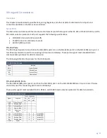
background image

pg. 26


INPUT PWR Connector 

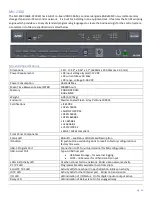
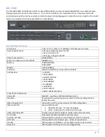
The MU-1300, MU-2300 and MU-3300 controllers feature a 2-pin 3.5 mm Phoenix connector with screw retention for 

providing DC power to the controller. The suggested power supply for the MU-series controllers is a 13.5 VDC 6.6 A 

output, suitable for 50° C. 

Preparing Captive Wires 

You will need a wire stripper and flat-blade screwdriver to prepare and connect the captive wires. 

NOTE: Never pre-tin wires for compression-type connections. 

1.


Strip 0.25 inch (6.35mm) of insulation off all wires. 

2.


Insert each wire into the appropriate opening on the connector (according to the wiring diagrams and connector 

types described in this section). 

3.


Tighten the screws to secure the wire in the connector. Do not tighten the screws excessively, as doing so may 

strip the threads and damage the connector. 
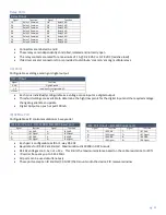
ID Pushbutton


All MU-series controllers feature an ID pushbutton which you can use to reset the default settings on the controller or 

restore the controller to its factory firmware image.  The Status LED will indicate the action performed by changing 

color. 

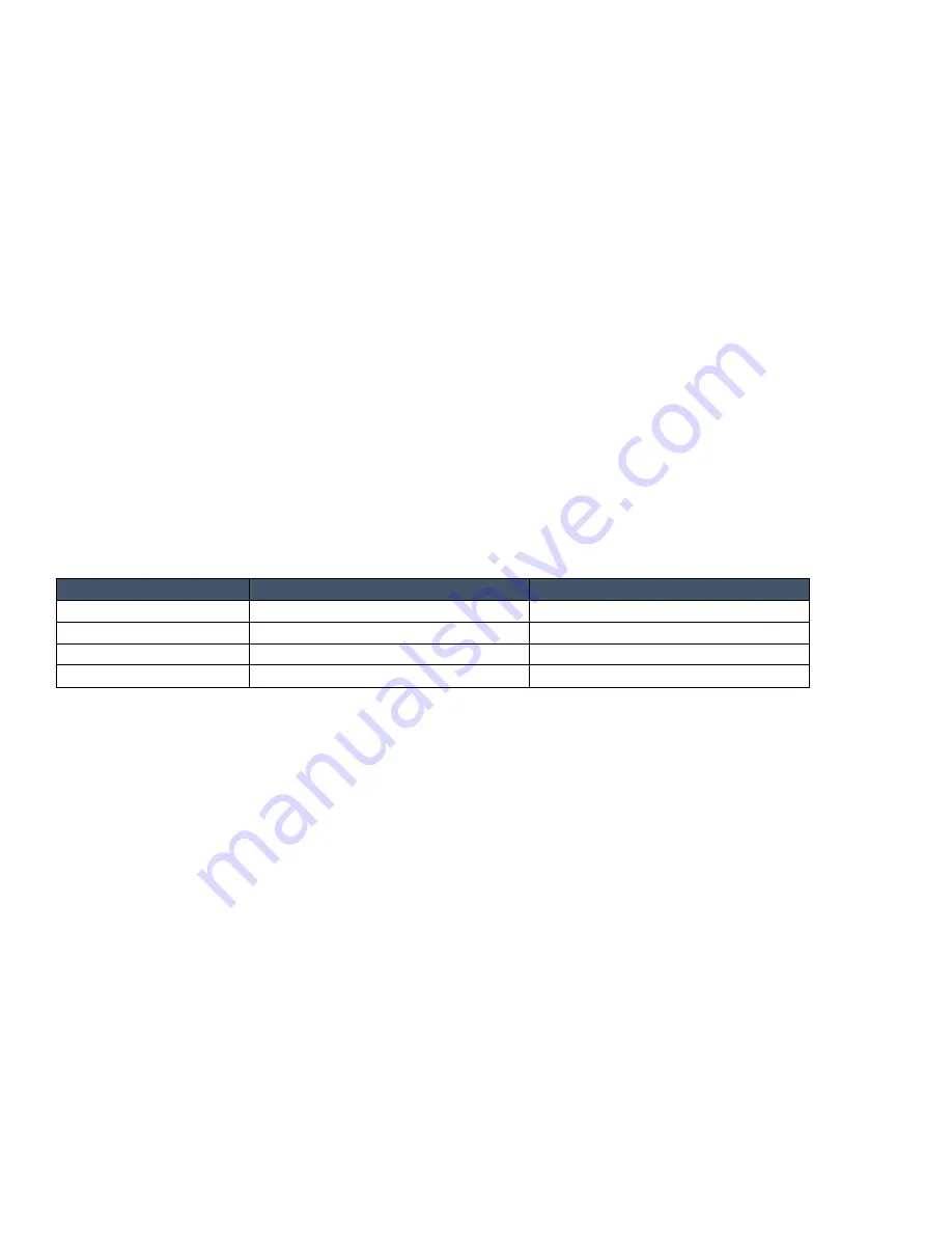
The ID Pushbutton functionality is as follows: 

ID Button Hold Duration  Status LED color 

Function Performed on Release 

Not held 

Green, blinking if scripts are running 

Running normally 

  0 – 10 seconds 

White, fast blinking 

Running normally, ID broadcast sent 

10 – 20 seconds 

Amber, fast blinking 

Configuration Reset (see below) 

20 + seconds 

Red, fast blinking 

Factory Firmware Reset (see below) 


A configuration reset performs the following operations: 


All user scripts (Python, Groovy, JavaScript and Node-RED) and libraries are deleted 


All manually installed extensions are uninstalled 


All manually configured repositories are removed 


All device instance files are removed 


All Plug-in configuration items are reset to their defaults 


All SMTP servers are removed 


ICSP authentication/encryption returns to "off" 


All bound NDP devices are unbound (TBD) 


All IRL files are removed 


All installed HiQnet AudioArchitect files are removed 


HiQnet node id returns to default 


All Duet module .jar files are removed 


Network configuration is returned to defaults 


LAN returns to DHCP client mode, hostname returns default value 


ICSLan returns to DHCP Server mode on octets 198.18.0.x 


802.1x is disabled 


Network time is disabled  


NTP servers are cleared 


Time will coast using the real-time clock 

Summary of Contents for AMX MU Series

Page 1: ...pg 1 Instruction Manual MU Series Automation Controllers...

Page 2: ...tic charges as possible Grounding straps conductive smocks and conductive work mats are specifically designed for this purpose These items should not be manufactured locally since they are generally c...

Page 3: ...qualified service personnel Servicing is required when the apparatus has been damaged in any way such as power supply cord or plug is damaged liquid has been spilled or objects have fallen into the a...

Page 4: ...ed under the 2006 66 EC European Directive which cannot be disposed of with normal household waste Please dispose of any used batteries properly following any local regulations Do not incinerate WARNI...

Page 5: ...nd can radiate radio frequency energy and if not installed and used in accordance with the instructions may cause harmful interference to radio communications However there is no guarantee that interf...

Page 6: ...ea level it can only be used in locations below 2000 meters above sea level Using the device above 2000 meters could result in a potential safety hazard This logo applies to electronic information pro...

Page 7: ...tion for electrical and electronic equipment consists of the crossed out wheeled bin as shown below This product must not be disposed of or dumped with your other household waste You are liable of dis...

Page 8: ...MU 1300 14 MU 1300 SPECIFICATIONS 14 MU 2300 16 MU 2300 SPECIFICATIONS 16 MU 3300 18 MU 3300 SPECIFICATIONS 18 MOUNTING THE CONTROLLER 20 MOUNTING THE MU 2300 AND MU 3300 20 INSTALLING THE CONTROLLER...

Page 9: ...25 USING THE ICSLAN NETWORK 25 ICSLan Network Settings 25 DHCP Server 25 Opening LAN and ICSLAN Sockets from Code 25 LAN 10 100 PORT 25 IPv4 25 IPv6 25 INPUT PWR CONNECTOR 26 PREPARING CAPTIVE WIRES...

Page 10: ...orite sites like Stack Overflow are there for reference and help Duet Module and Driver Design Module support The MU series platform still supports Duet modules This gives you control of 1000s of devi...

Page 11: ...x 5 1 8 42 16 mm x 147 32 mm x 130 81 mm DIN Rail mountable with DIN Rail Clip AMX CAC0001 4 GB DDR3 RAM 8 GB eMMC Storage 2x USB 2 0 Type A Host port 1x USB Type C program port MU 2300 AMX CCC023 1...

Page 12: ...Between Failure MTBF 100000 hours Memory 4 GB DDR3 RAM 8 GB eMMC Weight 1 26 lbs 572g Enclosure Powder Coated Steel Gray Pantone 10393C Certifications ICES 003 CE EN 55032 AUS NZ CISPR 32 CE EN 55035...

Page 13: ...network USB Host Port 2x Type A USB host port USB Mass Storage for external logging FLIRC IR Receiver for IR hand control input General Specifications Operating Environment Operating Temperature 32 F...

Page 14: ...ltage 9 18 VDC Power Consumption 26 Watts Max Mean Time Between Failure MTBF 100000 hours Memory 4 GB DDR3 RAM 8 GB eMMC Weight 1 58 lb 718g Enclosure Powder Coated Steel Gray Pantone 10393C Certifica...

Page 15: ...n double stack Phoenix connector All remaining device control connections Lower 10 pins RS 232 422 485 plus hw handshaking power Upper Left 6 pins 4 Input Output plus Ground and Power Upper Right 4 pi...

Page 16: ...Gray Pantone 10393C Certifications ICES 003 CE EN 55032 AUS NZ CISPR 32 CE EN 55035 CE EN 62368 1 IEC 62368 1 UL 62368 1 VCCI CISPR 32 RoHS WEEE compliant Front Panel Components Status LED RGB LED se...

Page 17: ...Handshaking CTS Clear to Send for Hardware Handshaking TXD Unbalanced line output for RS 232 RXD Unbalanced line input for RS 232 GND Signal ground for RS 232 Relays 1 4 3 5mm Phoenix 8 pin connector...

Page 18: ...Gray Pantone 10393C Certifications ICES 003 CE EN 55032 AUS NZ CISPR 32 CE EN 55035 CE EN 62368 1 IEC 62368 1 UL 62368 1 VCCI CISPR 32 RoHS WEEE compliant Front Panel Components Status LED RGB LED see...

Page 19: ...to Send for Hardware Handshaking TXD Unbalanced line output for RS 232 RXD Unbalanced line input for RS 232 GND Signal ground for RS 232 Relays 1 8 3 5mm Phoenix 8 pin connector 4 pairs Contact Closu...

Page 20: ...installation test the incoming wiring by connecting the Controller s connectors to their terminal locations and applying power Verify that the unit is receiving power and functioning properly Disconne...

Page 21: ...standard USB cabling to connect to any mass storage or peripheral devices FIG 10 USB Type A host port on MU 1300 Left and MU 2300 MU 3300 Right LEDs This section details the various LEDs on the front...

Page 22: ...t SERIAL LEDs The MU 2300 has two sets of four LEDs TheMU 1300 has two sets of two LEDs RELAYS LEDs The RELAYS LEDs light red to indicate that the corresponding relay port is active The light toggles...

Page 23: ...and displays These ports support most standard RS 232 communication protocols for data transmission The following table lists the pinouts for the RS 232 ports RS 232 Port Pinout Signal Function GND Si...

Page 24: ...nput or a digital output Threshold settings are available to determine the high low points for the digital input and the required voltage change to generate an update Digital Output can push or pull 1...

Page 25: ...ill serve IP addresses to any connected devices set to DHCP mode The DHCP server can be disabled from the MU controller s built in web server The DHCP address range is assigned to half the available I...

Page 26: ...color The ID Pushbutton functionality is as follows ID Button Hold Duration Status LED color Function Performed on Release Not held Green blinking if scripts are running Running normally 0 10 seconds...

Page 27: ...to their default 9600 8 data bits 1 stop bit No parity 422 485 disabled All I O s return to digital input mode with default threshold values A Factory Firmware reset includes a Configuration Reset and...

Page 28: ...arks registered trademarks of their respective companies AMX does not assume responsibility for errors or omissions AMX also reserves the right to alter speci cations without prior notice at any time...

Reviews: