background image


12 


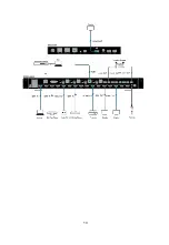
streaming device, CCTV etc.) to the HDMI input ports 1-8 of the matrix.   

Suggestion:

 Please insert and extract cables carefully with the power 

SWITCHED OFF. 
Power is passed along transmissions so connecting and disconnecting 
cables while powered may cause damage to circuitry or possible injury. 
2.  Firmly connect HDMI OUT 1-8 of the matrix to HDMI IN of 4K or HD 

display devices, make sure all sources and displays are compatible and 
correctly configured. 

3.  Firmly connect AUDIO OUT 1-8 of the matrix to audio devices such as 

amplifier. 

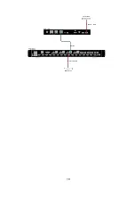
4.  Connect a HDBT Receiver to the HDBT port via Cat X cable. 
5.  Insert the matrix AC power cord and power on matrix by pressing power 

button on the front panel. Front panel LEDs will show matrix model name 
to indicate that the matrix is ready for operation. 

Note:

 Remember, always power off the matrix before unplugging any HDMI 

cables – follow last on, first off protocol. 
6.  Switch between sources and displays using the matrix front panel buttons, 

via IR remote control, through serial RS232 or LAN. 

7.  If IR extension is required, connect the IR Receiver Cable to the matrix IR 

EXT port, make sure the IR receiver eye is placed in clear view of the 
handset used to control.

Summary of Contents for AMX PR01-0808

Page 1: ...Version V1 0 2 PR01 0808 Precis 8x8 HDMI 4K60 with 4 HDBaseT User Manual...

Page 2: ...to overheating do not obstruct the unit s ventilation openings with newspapers tablecloths curtains and similar items 4 Do not install near any heat sources such as radiators heat registers stoves or...

Page 3: ...will not occur in a particular installation If this equipment does cause harmful interference to radio or television reception which can be determined by turning the equipment off and on the user is...

Page 4: ...ation and Wiring 11 Installation 11 Wiring 11 Front Panel Control 14 Remote Control 16 System Code Switch 17 RS232 Operation 18 RS232 Pinout 18 RS232 Pass Through 18 NetLinx Control 20 Device Number a...

Page 5: ...2 Firmware Upgrade 42 Before You Start 42 Transferring KIT Files 43 Trouble Shooting 45 Steps of Regular Troubleshooting Routine 45 Warranty Terms and Conditions 46...

Page 6: ...IR RS232 Web GUI and NetLinx DIP switch is also provided for manual EDID adjustment As a compact 1U stand alone 8x8 HDMI matrix it offers the convenience of future ready Ultra HD A V switching and di...

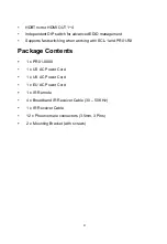
Page 7: ...switching when working with SCL 1 and PR01 RX Package Contents 1 x PR01 0808 1 x US AC Power Cord 1 x UK AC Power Cord 1 x EU AC Power Cord 1 x IR Remote 4 x Broadband IR Receiver Cable 30 50 KHz 1 x...

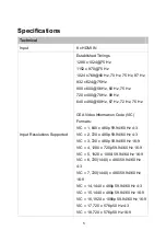
Page 8: ...75 Hz CEA Video Information Code VIC Formats VIC 1 640 x 480p 59 94 60 Hz 4 3 VIC 2 720 x 480p 59 94 60 Hz 4 3 VIC 3 720 x 480p 59 94 60 Hz 16 9 VIC 4 1280 x 720p 59 94 60 Hz 16 9 VIC 5 1920 x 1080i 5...

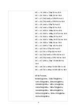
Page 9: ...7 30 Hz 16 9 VIC 39 1920 x 1080i 50 Hz 16 9 VIC 41 1280 x 720p 100 Hz 16 9 VIC 42 720 x 576p 100 Hz 4 3 VIC 43 720 x 576p 100 Hz 16 9 VIC 44 720 1440 x 576i 100 Hz 4 3 VIC 45 720 1440 x 576i 100 Hz 16...

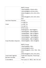
Page 10: ...mats 800x600 60Hz 1024x768 60Hz 1280x768 60Hz 1280x800 60Hz 1280x960 60Hz 1280x1024 60Hz 1360x768 60Hz 1366x768 60Hz 1400x1050 60Hz 1440x900 60Hz 1600x900 60Hz 1600x1200 60Hz 1680x1050 60Hz 1920x1200...

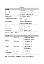
Page 11: ...evice Dimension W x H x D 440mm 43 5mm 320mm 17 32 x 1 71 x 12 60 Product Weight 0 9kg 1 98lb Certification CE FCC ETL PSE RCM Transmission Distance Cable Type Range Supported Video Cat 5e 6 100m 328f...

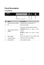
Page 12: ...R IR receive window 3 Select buttons with LED White Selects the input and output channels Left Right buttons are used to select outputs UP Down buttons are used to select inputs 4 Enter button with LE...

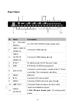
Page 13: ...on port for IR Receiver Cable 5 EDID DIP Switch for EDID management 6 LAN 10 100 Connect to control system used for Web UI Telnet controlling Thor commands controlling 7 RS232 DB9 port 8 IR IN Connect...

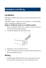
Page 14: ...itable location 1 Attach the installation bracket to the enclosure using the screws that were provided in the package separately 2 The bracket is attached to the enclosure as shown 3 Repeat steps 1 2...

Page 15: ...to audio devices such as amplifier 4 Connect a HDBT Receiver to the HDBT port via Cat X cable 5 Insert the matrix AC power cord and power on matrix by pressing power button on the front panel Front pa...

Page 16: ...13...

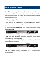
Page 17: ...y for operation Step 1 Press the Left or Right button to select output channel after the selection is complete the corresponding LED of the output channel will blink slowly For example press the Right...

Page 18: ...15 Step 3 Press the Enter button to confirm the selection after the selection takes effect the LED stops blinking...

Page 19: ...vious and next buttons Scrolls between the input sources The previous button means the previous input while the next button means the next input When using the matrix remote point it directly at the m...

Page 20: ...ices such as TV DVD or the other matrix the matrix is capable of switching between two distinct IR system codes to allow the IR remote control the matrix without interference Basically if the system c...

Page 21: ...rough To start RS232 pass through between PR01 0808 and a Receiver e g PR01 RX 1 Connect a RS232 Device RS232 Device 1 to RS232 port of PR01 0808 using a RS232 cable 2 Connect another RS232 Device RS2...

Page 22: ...19...

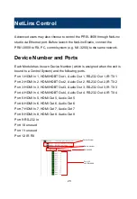
Page 23: ...llowing ports Port 1 HDMI In 1 HDMI HDBT Out 1 Audio Out 1 RS 232 Out 1 IR TX 1 Port 2 HDMI In 2 HDMI HDBT Out 2 Audio Out 2 RS 232 Out 2 IR TX 2 Port 3 HDMI In 3 HDMI HDBT Out 3 Audio Out 3 RS 232 Ou...

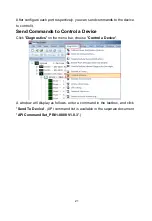
Page 24: ...control it Send Commands to Control a Device Click Diagnostics on the menu bar choose Control a Device A window will display as follows enter a command in the textbox and click Send To Device API com...

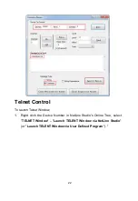
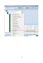
Page 25: ...t Control To launch Telnet Window 1 Right click the Device Number in NetLinx Studio s Online Tree select TELNET Window Launch TELENT Window via NetLinx Studio or Launch TELENT Window via User Defined...

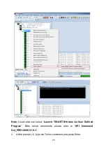
Page 26: ...3 Note Users also can select Launch TELNET Window via User Defined Program More telnet commands please refer to API Command Set_PR01 0808 V1 0 3 2 At the prompt type the Telnet command and press Enter...

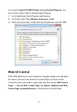
Page 27: ...Select the check boxes Telnet Client and Telnet Server and click OK Web UI Control PR01 0808 offers users a web interface for changing settings and controlling the matrix Users can enter the Web UI Co...

Page 28: ...25...

Page 29: ...e Tree select Web Control Page Launch Web Control Page via NetLinx Studio or select Launch Web Control Page via Default Browser The following page will pop up Enter the default password admin and clic...

Page 30: ...27 Web UI Introduction Matrix Control The Matrix Control submenu is used to perform the following tasks Switch Preset Switch The Switch manages the connection configurations of displays and sources...

Page 31: ...epresents that input and output are routed All Route all outputs to one input None Route output to none turn off output Presets Only matrix inputs outputs selection states can be saved as presets and...

Page 32: ...tting EDID Setting HDCP Support Port Name Preset Name Network Change Password Telnet SSH Account Telnet Service SSH Service ICSP Parameter System Save and Load Setting Update Status Update Web UI Log...

Page 33: ...30...

Page 34: ...on the Output drop down menu to select the output which you want to set Click Display On to send CEC command to power on the display connected to the output Click Display Off to send CEC command to p...

Page 35: ...or more than 2 minutes the display will power off automatically If you click the button OFF this function is free Note This function is valid only if the display supports CEC control and the time rang...

Page 36: ...33 Click Read to read EDID Change EDID settings through the input drop down menu click Apply to make the change effective...

Page 37: ...FF Input port do not support HDCP Port Naming Give the ports different names which will be easier for users to remember user can modify port names in this column Click Save to save the changes click R...

Page 38: ...of all names is limited to 15 characters letters numbers or space each Network In Network Column you can set device IP mode DHCP When enabled the IP address of the PR01 0808 will be assigned automatic...

Page 39: ...must be 4 to 16 characters in length alphanumeric only Telnet SSH Account Telnet SSH Account is used to configure the user name and password of the account For Telnet Account the default user name and...

Page 40: ...37 Telnet Service In this column users can select telnet Service Disable or Enable Enable is default SSH Service In this column users can select SSH Service Disable or Enable Enable is default...

Page 41: ...ystem Number Use the Online Tree to determine it By default it is disabled to configure Device Number Use the Online Tree to determine it By default it is disabled to configure Click APPLY to your set...

Page 42: ...of the box popped to reset the device to factory defaults Save and Load Setting In this column users can save settings and load settings Save Settings Save current settings as a setting file to be sa...

Page 43: ...he firmware of device Update Web UI In this column users can update Web UI Step 1 Browse for the bin file Step 2 Click on Update button Note Module will update and reboot automatically Please wait for...

Page 44: ...41 LOG In this column users can hide or show the log in the bottom of the page Firmware In this column users can check the firmware version...

Page 45: ...e is connected from PR01 0808 to the same network as the control system b Verify the PR01 0808 unit is powered on 4 Launch NetLinx Studio and open the Online Tree 5 Bind the target device to the integ...

Page 46: ...ory path is displayed in the Location text box KIT files in the target directory display under Files 3 Select the appropriate KIT file from the list 4 Enter the Device and System numbers see Device Nu...

Page 47: ...the process of firmware upgrading 7 The device will restart automatically do not need to power cycle it Note The upgrade process will last 1 hour Do not power off the device until it has been success...

Page 48: ...ormally when connecting source to display devices directly 4 Cable Plug in and out HDMI Cat X cable or try another HDMI Cat X cable Please make sure the specific cable length is within available trans...

Page 49: ...t that the product is repaired dismantled or altered by anyone that is not from a AMX authorized service partner The defects are caused by the fact that the product is used or handled improperly rough...

Page 50: ...AMX Office Address 3000 Research Drive Richardson TX 75082 Website www amx com Tel 800 222 0193 469 624 8000 1 469 624 7400 Fax 469 624 7153...

Reviews: