background image

AXYS

®

 Octadrive DSP-DN User Manual rev 2.0

201703/ODSPDN_2.0

13

Ambient Temperature Sensor

The Octadrive DSP-DN is equipped with a loudspeaker frost 
protection system which activates the internally-generated  
pilot tone (analogue outputs only) if the ambient 
temperature drops below a pre-determined threshold. This 
is passed to the system’s power amplifiers and produces 
current in the loudspeaker voice coils, warming the drivers 
slightly. The function may be enabled via WinControl.

This feature is also provided in certain other AXYS

®

 products: 

in particular, Intellivox loudspeakers. If the Octadrive 
DSP-DN is being used with third-party amplifiers, or with 
loudspeakers from the AXYS

®

 Sound Reinforcement range 

(which do not have this feature), we recommend that frost 
protection is enabled if the loudspeakers are in a location 
where low ambient temperatures are possible.

Frequency and level of the pilot tone generator are software 
configurable. Note that the actual pilot tone level will be 
affected by the ‘high/low output gain mode’ setting.

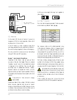
If this function is required, an external ambient temperature 
sensor (available as an option – see below) should be 
wired to the 2-pin 3.81 mm-pitch screw-terminal ‘Temp’ 
connector [16] using screened two-core cable. Connect 
the ‘+’ terminal of the sensor to the ‘+’ pin of the Temp 
connector, and both the ‘-‘ terminal of the sensor and 
the screen of the cable to the pin of the Temp connector 
marked with an earth (ground) symbol  .

A suitable AXYS

®

 temperature sensor (combined with 

an ANS microphone) is available (Part No. 971181101 
Ambient Mic and Temperature sensor). This should be 
wired using twin twisted-pair cable with an overall screen. 
Use one pair for the microphone and the other for the 
temperature sensor. Connect ‘ntc’ on the sensor to ‘+’ on 
the Temp connector and ‘AGND’ on the sensor to the Temp 
connector pin marked with an earth (ground) symbol 
. Connect the microphone pair to the ‘+’ and ‘-‘ pins of 
the Ambient Microphone input. The cable’s overall screen 
should be connected to the pin of the Ambient Microphone 
input marked with an earth (ground) symbol  .

External Control Voltage Input

The Octadrive DSP-DN is fitted with an external control 
port [17] (marked ‘VCI’ on the rear panel), which can be 
used to load an internal “emergency” configuration in the 
form of a preset from memory in the event of, e.g., network 
failure.

The unit’s internal memory has provision for an 
“emergency” configuration preset to be stored, and 
automatically recalled and loaded under certain 
programmable conditions. This preset is defined and 
configured in WinControl. This is a useful facility where 
the audio system is to be used for emergency evacuation 
messages. (See “Presets” on page 17 and the WinControl 
Help files for more information on Presets.) The emergency 
preset may also be recalled by an external DC voltage at 
the VCI input. This input is isolated by an opto-coupler. 
The emergency preset will be loaded either on a logic 
high (5 - 24 VDC) or a logic low (0 - 2 VDC) at the input 
(programmable in WinControl).

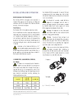
The connector is a 2-pole 3.81 mm-pitch screw-terminal 
type. Be careful to observe the ‘+’ and ‘-‘ symbols on this 
connector when wiring to external equipment.

Summary of Contents for AXYS Octadrive DSP-DN

Page 1: ...ure of sound reinforcement Installation User Manual AXYS Octadrive DSP DN Dante 8 channel line driver Part No 391035 Note that this manual is valid for hardware series 2 Octadrive DSP DN with serial number 14900101 and up are hardware series 2 ...

Page 2: ...0 5301 KK Zaltbommel The Netherlands Tel 31 418 515583 Fax 31 418 518077 Zaltbommel March 2017 User s Notice and Disclaimer No part of this manual may be reproduced transmitted transcribed stored in a database system or translated without the express written permission of Duran Audio BV Documentation kept by the end user for back up purposes is excluded from the above All products and corporate na...

Page 3: ...Wiring Details 9 AC Mains 9 Back up Supply 10 Analogue Audio Connections 10 Analogue Inputs 10 Analogue Outputs 10 ANS Paging Microphone 11 Failure Relay 11 Dante and Control Interface 12 Ambient Temperature Sensor 13 External Control Voltage Input 13 DSP Section Overview 14 Level Controls 15 EQ Adjustment 15 Delay 15 Autogain 15 Surveillance Functions 15 Auto Input Switching 15 Failure Relay 16 P...

Page 4: ...ence receptacles and the point where they exit from the apparatus 11 Only use attachments accessories specified by the manufacturer 12 Unplug this apparatus during lightning storms or when unused for long periods of time 13 Refer servicing to qualified service personnel Servicing is required when the apparatus has been damaged in any way such as power supply cord or plug is damaged liquid has been...

Page 5: ...ed controlled and monitored using AXYS WinControl software via the Dante Ethernet interfaces Features Eight independent low impedance transformer balanced analogue outputs 19 dBV drive capability Two transformer balanced analogue inputs 0 dBV Ambient Noise Sensing ANS Paging mic input Headphone monitoring of all analogue inputs and outputs Integral dual redundant Dante audio networking card Sixtee...

Page 6: ...1 Out 1 Input 2 Dante 18 x Digital Outputs ANS Paging Mic Micro Controller Analogue Pilot detect Status LEDs To Outputs Digital Pilot detect x16 PSU Internal Supplies Mains DC Back up Supply Out 2 Out 3 Out 4 All Analogue signals Rotary Selector Gain Headphone Output LED Indication Out 5 Out 6 Out 7 Out 8 Control Voltage Ambient Temperature Sensor External Failure Relays AxysBridge Serial Bridge D...

Page 7: ...uously monitored for pilot tone with the same auto switching arrangement as the analogue inputs All active inputs as enabled via WinControl are routed to all output channels Pilot tone generation is available on both the analogue and digital audio outputs The frequency and level settings are independently software configurable for both of these separate output types The microphone input can be use...

Page 8: ...l Bridge activity LED 11 Mic Level LED 12 Identify LED rear 13 Dante Primary 14 Dante Secondary 15 ANS Paging Mic 16 Ambient temperature sensor 17 Control voltage input 18 Failure relay contacts 1 19 Failure relay contacts 2 20 Input 1 21 Input 2 22 Output 1 23 Output 2 24 Output 3 25 Output 4 26 Output 5 27 Output 6 28 Output 7 29 Output 8 30 Back up Supply LED rear 31 Back up Supply connector 32...

Page 9: ...the territory are of a different type the correct type of mains plug should be substituted carefully observing the following cable colour codes CONNECT COLOUR EUROPE COLOUR US Live Brown Black Neutral Blue White Earth Ground Green Yellow Green Numbers in square brackets refer to the figs 2 3 4 on page 8 The Octadrive DSP DN incorporates a universal PSU and will operate on all AC mains voltages fro...

Page 10: ...gue Inputs The two transformer balanced Analogue inputs are on the connectors 20 and 21 As with other AXYS products e g Intellivox loudspeakers and Industry Amps the normal routing of the input signals may be altered by enabling auto input switching from WinControl In normal operation both inputs route internally to all eight outputs If auto input switching is enabled only Input 1 is used If auto ...

Page 11: ...tivate the processed microphone Dante transmit channel For monitored PTT operation the DC impedance between PTT and GND should be 10k Ω activated respectively 20k Ω deactivated PTT control by network command is also supported this operates when PTT is unconnected PTT Switch 2 x 10kΩ resistors fig 7 PTT Switch Monitoring Circuit The PTT switch operation can either be monitored or un monitored When ...

Page 12: ...the local Ethernet switch es However in many installations the network connection from within a rack to an Ethernet switch will be via structural cabling In this case wire mating RJ 45 plugs not supplied as shown below fig 9 Dante Connectors This is the T 568B standard preferred T 568A standard is also used and uses different colour mapping PIN CAT 5e CORE 1 White Orange 2 Orange 3 White Green 4 B...

Page 13: ...ure sensor combined with an ANS microphone is available Part No 971181101 Ambient Mic and Temperature sensor This should be wired using twin twisted pair cable with an overall screen Use one pair for the microphone and the other for the temperature sensor Connect ntc on the sensor to on the Temp connector and AGND on the sensor to the Temp connector pin marked with an earth ground symbol Connect t...

Page 14: ...AIN DELAY EQ Dante xmt 2 Dante xmt 1 Dante xmt 3 Dante xmt 4 Dante xmt 5 Dante xmt 6 Dante xmt 7 Dante xmt 8 OPTIONAL EXTERNAL MICROPHONE Dante xmt 18 Dante xmt 17 To Dante Outputs Dante xmt 11 Dante xmt 12 Dante xmt 10 Dante xmt 9 Dante xmt 14 Dante xmt 15 Dante xmt 16 Dante xmt 13 INPUT 1 INPUT 2 INPUT 3 INPUT 4 INPUT 5 INPUT 6 INPUT 7 INPUT 8 INPUT 9 INPUT 10 INPUT 11 INPUT 12 INPUT 13 INPUT 14...

Page 15: ...t and output equalisers Delay Delay may be inserted in any or all of three locations in the audio signal chain Each output channel may have up to 43 6 s of delay Additionally an overall unit delay of up to 21 8 s may be inserted at the main volume control stage Furthermore each analogue input may have up to 1 3 s of delay Autogain The DSP section includes an autogain algorithm which can be set to ...

Page 16: ...ld may be set between 10 dBFS and 60 dBFS The Octadrive s action on non detection of a pilot tone can be configured via WinControl A fault condition can be flagged and or the input can be set auto switch to that with the next priority A notch filter should be inserted to suppress the pilot tone if its frequency is less than half the internal processor s sample frequency Fs 2 typically 24 kHz If th...

Page 17: ...SP failure is reported to the WinControl server as well as triggering the external failure relay if configured to do so Status LEDs The front panel carries a set of seven LEDs showing the status of various unit functions From left to right Power Supply green 5 illuminates when the Octadrive DSP DN is connected to the mains supply power is switched on and the internal mains operated PSU functions n...

Page 18: ... one of the ten green LEDs 3 being illuminated The level in the headphones may be adjusted with the Volume control 1 Dante Configuration The Dante card fitted to the Octadrive DSP DN is self organising and requires no adjustments However for configuring systems with multiples of Octadrive DSP DN units each device must have been assigned a unique IP address This as well as the audio routing is defi...

Page 19: ...lways connect this terminal 2 Reduction of RF emission Although the Octadrive DSP DN electronics are well shielded and external connections are decoupled to prevent RF emission from the internal high speed digital circuits this protection will not work properly if the chassis is not connected to ground 3 RF Immunity RF currents induced in the signal cables by external RF fields are effectively sho...

Page 20: ...DURAN AUDIO BV Koxkampseweg 10 5301 KK Zaltbommel The Netherlands tel 31 418 515583 fax 31 418 518077 http www duran audio com Info duran audio com ...

Reviews: