background image

Networked PIP Series

Reference Manual

page 5

Controls, Indicators and Connectors

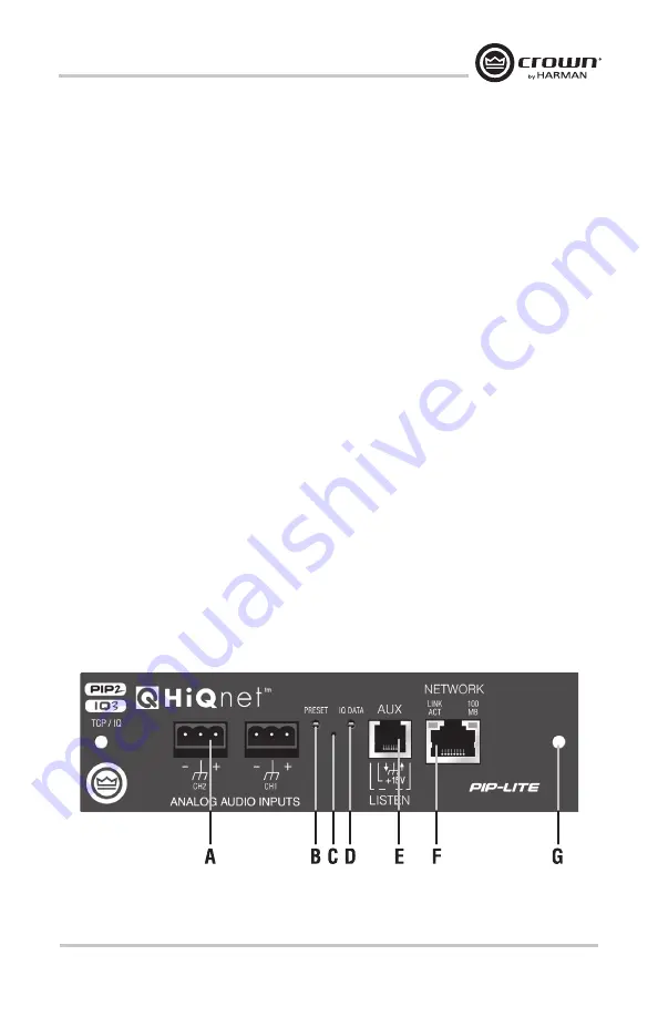
PIP-Lite

A.  Balanced Audio Input Connectors


3-pin removable barrier-strip connectors, one per channel.

B.  Preset Indicator


Signals the number of the current preset, if active, by flashing a series of flashes 

equal to the current preset number. The indicator will also flash twice a second when 

receiving an locate command.

C.  Reset/Preset Switch


Used to change presets, restore settings to factory default or restore all the presets to 

the factory defaults. During operations of the switch, the Data indicator flashes as an 

aid to the user.

D.  Data Indicator 


Flashes when the PIP-Lite receives a valid command that is addressed to the PIP-Lite.  

The indicator will also flash twice a second when receiving an locate command. 

E.  AUX Connector


AUX input, AUX output, and Listen Bus/Foldback.

F.  Network Connector


The network connector is a standard RJ-45 connector that allows the PIP-Lite to 

connect to an Ethernet network. Connection is made using a standard Category 5 

or better cable to a network switch port. For compliance with emission regulations, 

the supplied ferrite core must be placed on the CAT5 cable, with the cable making 

two passes through the core as shown in the figure below. The Link Activity LED 

indicates data activity on the network line. The 100 MB LED indicates that the data 

is at 100 Megabits.

G.  Mounting Holes

PIP-Lite Controls, Indicators and Connectors 

(Note: Actual Product Artwork May Vary Slightly)

www.audiovias.com

Summary of Contents for crown PIP Series

Page 1: ...nce If special assistance is needed beyond the scope of this manual or the software online help please contact the Crown Technical Support Group The information provided in this manual was deemed accurate as of the publication date However updates to this information may have occurred To obtain the latest version of this manual please visit the Crown website at www crownaudio com Trademark Notice ...

Page 2: ...s not expressly approved by the party responsible for complicance could void the user s authority to operate the euqipment NOTE This equipment has been tested and found to comply with the limits for a Class B digital device pursuant to part 15 of the FCC Rules These limits are designed to provide reasonable protection against harmful interference in a residential installation This equipment genera...

Page 3: ...ty Product Family Standard for Audio Video Audio Visual and Entertainment Lighting Control Apparatus for Professional Use Part 2 Immunity EN 61000 4 2 2008 Ed 2 0 EMC Compatibility Product Family Standard for Audio Video Audio Visual and Entertainment Lighting Control Apparatus for Professional Use Part 2 Immunity EN 61000 4 3 2010 Ed 3 2 Radiated Radio Frequency Electromagnetic Immunity Environme...

Page 4: ...rrite core to the 18 pin cable B before connecting The 20 pin cable A should go to the connector further inside and away from the corner AJ9 and the 18 pin cable should connect to the one closest to the corner BJ5 Important Be careful when attaching the ribbon cable to the connector Applying pressure to an improperly seated connector could cause the keying tabs which ensure proper pin alignment to...

Page 5: ...ite receives a valid command that is addressed to the PIP Lite The indicator will also flash twice a second when receiving an locate command E AUX Connector AUX input AUX output and Listen Bus Foldback F Network Connector The network connector is a standard RJ 45 connector that allows the PIP Lite to connect to an Ethernet network Connection is made using a standard Category 5 or better cable to a...

Page 6: ...s available through CobraNet F Preset Indicator LED flashes to signal the number of the current preset LED is green if the preset values have not been changed once loaded LED is yellow if the preset values have been changed since they were loaded The indicator will also flash twice a second when receiving an locate command G Reset Preset Switch Used to change presets restore settings to factory de...

Page 7: ...Signals the number of the current preset if active by flashing a series of flashes equal to the current preset number The indicator will also flash twice a second when receiving an locate command D Reset Preset Switch Used to change presets restore settings to factory default or restore all the presets to the factory defaults During operations of the switch the Data indicator flashes as an aid to ...

Page 8: ...wo screws Install the PIP into the Amplifier Carefully ground yourself to the chassis of the amplifier before installing the PIP it is a good idea to maintain ground contact between yourself and the amplifier while inserting the module into the amplifier Prepare the Cables Before using the AUX port and after the PIP Lite module has been installed into the amp make sure to pass the CAT5 cable twice...

Page 9: ...eak Connecting the ribbon cables with improper pin alignment will likely result in damage to the PIP module Mount the PIP Module in the Amplifier 1 With both cables firmly attached turn the PIP to an upright position Verify that the cables run untwisted between the amplifier and the PIP module 2 Insert the PIP module into the amplifier while taking care not to crimp pinch or stretch the ribbon cab...

Page 10: ...e keying tabs which ensure proper pin alignment to break Connecting the ribbon cables with improper pin alignment will likely result in damage to the PIP module 4 Set amplifier sensitivity to 26dB by placing both sensitivity switches in the center position 5 The Bridge Mono Mode is set via software leave the Mode switch in Dual and set the attenuator knobs to full clockwise wide open for all the f...

Page 11: ...U ONLY BLU Link is a digital audio bus that can only be used on a separate network The BLU Link bus audio bus is wired using standard CAT5e cable Connect the output of the London Soundweb BLU to the input BLU Link port Connect the BLU Link output to the next amplifier BLU Link input and repeat for all amplifiers The last amplifier in the chain must be connected back to the London Soundweb BLU Link...

Page 12: ...ctor is a power supply pin designed for use by the AUX input pin Since the AUX input floats low the AUX input can be triggered by just a simple switch closure between it and the AUX power pin No external power supply is needed to operate the AUX input under most conditions If the AUX input is used to sense an externally supplied voltage it must be scaled so that low inputs are between 0 and 1 6 VD...

Page 13: ... AUX output must actuate a larger relay The relay would then turn on the auxiliary equipment PIP USP4 CN AUX Output The AUX output on USP4 CN provides a relay rated at 1A 30 VDC which can be switched ON or OFF under software control In its basic mode the AUX output can be used to control auxiliary equipment To control AC line powered equipment the AUX output must actuate a larger relay The relay w...

Page 14: ...authorized service center or our factory All expenses in remedying the defect including surface shipping costs in the United States will be borne by us You must bear the expense of shipping the product between any for eign country and the port of entry in the United States including the return shipment and all taxes duties and other customs fees for such for eign shipments HOW TO OBTAIN WARRANTY S...

Page 15: ...g costs and other finance charges less a reasonable depreciation on the product from the date of original purchase War ranty work can only be performed at our autho rized service centers We will remedy the defect and ship the product from the service center within a reasonable time after receipt of the defec tive product at our authorized service center HOW TO OBTAIN WARRANTY SERVICE You must noti...

Page 16: ...www audiovias com ...

Reviews: