background image

27

Setting The Timer

1.  Select  timer  mode  by  briefly  pressing  the 

SET


button.

2. Press and hold 

SET

 until “TIMER” is displayed on 

the lower right hand side.

3. Press and hold 

SET

 until the P1 ☼ (sun symbol) 

and  the  time  display  flashes.  Set  the  hour  by 

pressing the ▲ (up arrow) and set the minutes by 

pressing the ▼ (down)
4. Briefly press 

SET

 for the next burner cycle time.

EXAMPLE: P1     (moon symbol) continue through 

P2 ☼(sun symbol) and P2     (moonsymbol).
5.  Once  all  four  (4)  times  are  set,  press 

OFF

 or 

simply wait to complete programming.

Lighting & Operation

           TEMP MODE - Daytime Temperature Mode

(appliance must be in standby mode; pilot ignited): 

The room temperature is measured and compared 

to  the  set  temperature.  The  flame  height  is 

automatically adjusted to achieve the daytime set 

temperature setting.


TEMP MODE - Night time setback temperature 

mode  (appliance  must  be  in  standby  mode;  pilot 

ignited)  The  room  temperature  is  measured  and 

compared  to  the  setback  temperature.  The  flame 

height is automatically adjusted to achieve the night 

time setback temperature setting.


TIMER  MODE  -  (appliance  must  be  in  the 

standby mode; pilot ignited) The timer setting allows 

you  to  set  two  (2)  burner 

ON

  times  and  two  (2) 

burner 

OFF

 times for every 24 hours.

NOTE:

 The display shows the set temperature 

every 30 seconds.

Changing the Mode of Operation

Briefly pressing the SET button changes the mode 

of operation in the following order: 

NOTE: “MAN”

 mode can also be reached by 

pressing  either  the  ▲(up  arrow)  or  the  ▼(down 

arrow)

and back to

“MAN” Mode- Manual Flame Height Adjustment

1.  Press ▲(up arrow) to turn on the main burner.

2.  Press ▲(up arrow) to increase the flameheight.

3.    Press  ▼(down  arrow)  to  decrease  the  flame 

height or to go to pilot standby.

NOTE: While pressing either button, a symbol 

indicating transmission appears on the display. The 

receiver  confirms  transmission  with  an  acoustic 

signal (or beep).

Setting The Temperature

1. Select either the        mode or the 

    mode 

by briefly pressing the SET button.

2.  Hold  the  SET  button  until  the  TEMP  display 

flashes.

3.  Set  the  desired  temperature  with▲or▼up  or 

down arrow button(s).

NOTE:

 4.5°C / 40°F is the min. temperature setting.

4. Press OFF or simply wait, and the display will go 

to the temperature control mode.

NOTE:

  To  turn  off  the  night  setback  temperature 

control, decrease the night time temperature until 

[---] appears on the display.

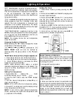
Radio Frequency Inteference

A frequency code is preset for the valve receiver 

and remote handset, but can be changed if you 

are experiencing interference from other devices. 

To change the code:

1. Change DIP switch position.

2. Press and hold the receiver’s reset button until 

you hear two (2) acoustic signals. After the second, 

longer, signal, release the reset button and within 

the  next  twenty(20)  seconds,  press  the▼(down 

arrow)  on  the  remote  handset  til  you  hear  and 

additional long signal that confirms the new code 

is set. ( above )

Dip Switch in Remote Handset 

Battery Compartment

RESET
Receiver Reset Button

Summary of Contents for FireLuxe Direct Vent

Page 1: ...on and service must be performed by a qualified installer service agency or the gas supplier INSTALLER Leave this manual with the appliance CONSUMER Retain this manual for future reference This applia...

Page 2: ...areil peut tre install dans une maison pr fabriqu e mobile d j install e demeure si kes r glements locaux le permettent Cet appareil doit tre uniquement avec las type de gaz indiqu sur la plaque signa...

Page 3: ...ts IMPORTANT SAFETY INFORMATION 4 SPECIFICATIONS 5 INSTALLATION 6 MASSACHUSETTS REQUIREMENTS 7 VENTING 8 ASSEMBLY 14 LIGHTING AND OPERATION 23 REMOTE CONTROL HANDSET OPERATION PROGRAMMING 26 MAINTENAN...

Page 4: ...of the appliance A commercially available hearth pad meets this requirement The appliance area must be kept clear and free from combustible materials gasoline and other flammable vapors and liquids Th...

Page 5: ...his appliance is equipped for use with the fuel type indicated on the rating plate Fuel conversion kits that include the necessary parts and instructions are available from your installer dealer or Ha...

Page 6: ...ve will also affect the venting requirements and you must be certain the location will allow compliance with the venting requirements shown on pages 8 13 You must also insure that your installation pr...

Page 7: ...carbon monoxide detector with an alarm must be installed on each additional level of the dwelling building or structure served by the appliance It shall be the responsibility of the property owner to...

Page 8: ...ed to the number designation this indicates that the position is fractionally between adjacent numbers For example 5 is one fourth the way between 5 and 6 To use the charts determine the horizontal ru...

Page 9: ...Exhaust C 3 Example 3 Fuel Natural Gas Vertical Rise 22 feet Horizontal Run 0 feet Elbows 0 none Equivalent Horizontal Run 0 feet Air Restrictor Setting E Exhaust Restrictor Setting 7 Inlet Air Exhaus...

Page 10: ...10 Venting Natural Gas Venting Horizontal Run In Feet Vertical Rise In Feet IF YOUR VENTING CONFIGURATION FALLS ABOVE THIS DOTTED LINE SEE PAGE 12...

Page 11: ...11 Venting Propane LP Gas Venting Vertical Rise In Feet Horizontal Run In Feet IF YOUR VENTING CONFIGURATION FALLS ABOVE THIS DOTTED LINE SEE PAGE 12...

Page 12: ...he FireLuxe may be vented through an existing fireplace chimney The fireplace opening must be at least 28 high All clearances to adjacent combustible materials including the mantel must be in conforma...

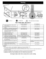
Page 13: ...13 Venting V Vent Terminal Vent Termination Clearances Venting terminals shall not be recessed into a wall or siding...

Page 14: ...off the pallet and set it near to its installation position Like any cast iron stove it is best to pick the stove up while adjusting its position rather than dragging it on its legs This reduces the...

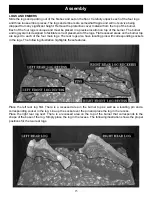
Page 15: ...rect placement of the logs Flat recessed areas on the burner top are keyed to each of the four main logs The rear logs also have locating pins with corresponding sockets in the logs The following illu...

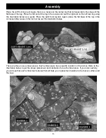
Page 16: ...Place the right front log last Again place the flat base of the log in the corresponding recess in the burner top per the illustration below There are three loose ember pieces Each ember piece has a...

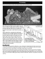
Page 17: ...n place with one hand and engage the three glass frame latches by pulling out and down while hooking them over the frame Top or Rear Vent The FireLuxe has provisions for either top or rear venting but...

Page 18: ...refully turn the front over Adjust the ashlip so that it is tight against the lower molding on the front Tighten the ashlip bolts Take care with an enamel stove to prevent chipping Replace the stove f...

Page 19: ...are manually modulating the flame up and down on a frequent basis There are three battery locations The electronic ignition module for the cooking burner is located behind an access panel located on...

Page 20: ...tain not to dislodge the wiring from the control module and be sure to place the module back it its original position after the batteries and cover are installed GAS CONNECTION The FireLuxe is shipped...

Page 21: ...justment in the section below that discusses the air inlet and exhaust outlet restrictors AIR INLET AND EXHAUST OUTLET RESTRICTORS The FireLuxe is equipped with externally adjustable restrictors for b...

Page 22: ...s shorten and become lighter in color No more than one full increment of adjustment should be used If no change in the flame appearance is noted after that consult with a Harman Stove Company represen...

Page 23: ...lly light the pilot 3 Push the OFF button on the remote handset to insure the appliance is off 4 Wait five 5 minutes to clear out any gas Then smell for gas including near the floor If you smell gas S...

Page 24: ...the pilot does not stay lit after several tries turn the main valve knob to OFF and proceed to step 7 6 Turn the MAN knob to the ON full counterclockwise position 7 If the appliance will not operate...

Page 25: ...G THE COOKING BURNER IS FOR ATTENDED USE ONLY DO NOT LEAVE ON UNATTENDED FOR ANY REASON WARNING CHILDRENANDADULTS SHOULD BEALERTED TO THE HAZARDS OF HIGH SURFACE TEMPERATURES AND SHOULD STAY AWAY TO A...

Page 26: ...y changes from farenheit 12 hour clock to Celsius 24 hour clock and vice versa Setting the Time Display and Timer Thermostat handsets 1 The display will flash after either a Installing the battery or...

Page 27: ...tion in the following order NOTE MAN mode can also be reached by pressing either the up arrow or the down arrow and back to MAN Mode Manual Flame Height Adjustment 1 Press up arrow to turn on the main...

Page 28: ...ny broken glass from the burner and logs 7 Install the new glass gasket onto the glass panel following the instructions included with glass panel 8 With the thin section of the glass gasket facing the...

Page 29: ...system to maximize heat delivered from the stove It is important that air flows freely through the convection air system and out the front and side air grills Do not place objects under the stove that...

Page 30: ...and or repairs including but not limited to remote controls filters fuses knobs glass ceramic brick panels ceramic fiber afterburners combustion packages door packing tile ceramic log sets paint batte...

Page 31: ...For replacement parts and customer service contact your Harman Stove Dealer Manufactured by 352 MOUNTAIN HOUSE ROAD HALIFAX PA 17032 R5 ver 06 23 12...

Reviews: