background image

30

3-90-233R24_11/13

8. 

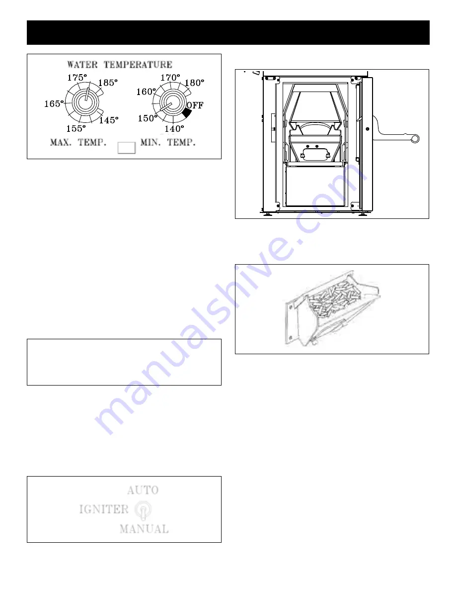
Turn the mIN. TEmP. dial 

on the control board to the 

desired Minimum temperature. This will start the lighting 

process  if  the  temperature  at  the  aquastat  sensor  is 

approximately 5° F. less than the set temperature on the 

MAX TEMP. dial.

9. 

Fill hopper

 with pellets and 

remove ashes

 as required.

Type of Fuel 

- Use pelletized wood only. The lower the 

ash content of the pellets the less cleaning that will be 

needed of the heat exchanger tubes. The cleaner these 

tubes are kept, the more efficient the boiler will be.

NOTE: Do not burn garbage, gasoline, naphtha, engine 

oil, or other inappropriate materials in this appliance.

Store pellets in the manufacturer’s wrapping until needed 

to prevent pellets from absorbing moisture. do not store 

fuel within the appliance installation clearances, or within 

the space required for fueling, ash removal, and other 

routine maintenance operations.

Operation

lighting A Fire manually

Lighting the fire manually will not be necessary unless the 

ignition system fails.

Follow steps 1 through 5 of the instructions for automatic 

lighting.
6.


Flip the Igniter Switch down 

into the “MANUAL-LIGHT” 

position. See Fig. 12.

7.  Open the firebox door to access the burnpot.

8. Fill the burnpot with pellets as shown. 

See Fig. 14. 

Only fill level with the front edge.


( ------- dO NOT OvErFIll ------- )

9.  Have matches or other ignition source ready.

10. Turn mode Selector

 to desired MIN TEMP setting.

This will start the combustion blower and allow the ESP to 

control  the  fire  in  relation  to  the  MAX TEMP  Dial  setting. 

(The MAX TEMP dial setting must always be set above the 

MIN TEMP setting) Once the fire is well established the MAX 

TEMP dial can remain on any temperature setting desired.

durINg mANuAl OPErATION:
SPECIAl NOTE: when the Switch is set to manual ignite 

position, the boiler will function as in auto mode, except 

the fire will not be allowed to go out. It will only be allowed 

to go to a minimum burn rate between the times the 

aquastat is calling for heat. This rate is about 

1.1 pound


of fuel per hour. If used in manual mode, be sure there 

is an overheat dump in place. Note that if the overheat 

dump zone does not provide sufficient cooling, and the 

water temperature reaches 220 deg, the feed motor will 

be forced to shut off. because the unit is set on manual 

Ignition, it will not re-ignite when the water temperature 

cools below the settings.

Fig. 12

Fig. 13

Never attempt to start a fire if there is no power or if 

the combustion blower is not operating. 

Never open the hopper lid during a fire if there is no 

power or if the combustion blower is not operating.

Fig. 14

Summary of Contents for HydroFlex 60 Pellet Boiler

Page 1: ...mit CETTE GUIDE D UTILISATION EST DISPONIBLE EN FRANCAIS CHEZ VOTRE CONCESSIONNAIRE DE HARMAN save these instructions Installation Operating Manual Model s HydroFlex 60 Pellet Boiler NOTICE SAVE THESE...

Page 2: ...Pellet Vent Combustion Blower Temperature Pressure Gauge Pressure Relief Valve Firebox Door Control Board Combustion Blower Cover Circuit Breaker Power Cord Heating System Supply Return either side R...

Page 3: ...rts 44 Start Up Quick Reference Back Cover Contains updated information Harman Central Heating Appliances are built and tested to be complete Home Heating solutions As with any Central Heat system a b...

Page 4: ...parate from the vent passage Outside Air Components Water Piping Supports Item 2 00 232044B secures to the boiler and gives the support needed for the expansion tank and circulator while keeping them...

Page 5: ...trol board The wires can be connected to the sensor with wire nuts or butt splice connectors Installation Boiler Kit Materials Refer to page 3 List of items shipped with the unit 1 3 4 Boiler Drain 1...

Page 6: ...re used or stored in quantities above that of normal use Installation Floor Protection The striped area indicates the minimum required floor protection area if the boiler is going to be placed on a co...

Page 7: ...l Alc ve Minimum Alcove Depth 60 1524 mm Profondeur de l Alc ve WARNING RISK OF FIRE Hearth Home Technologies disclaims any responsibility for and the warranty and agency listing will be voided by the...

Page 8: ...If you see deposits developing on the wall you may need to extend this distance to accommodate your installation conditions H A vent must not be installed within 3 feet 90 cm above a gas meter regulat...

Page 9: ...tween the layers This air space acts as an insulator and reduces the outside surface temperature to allow a minimum clearance to combustibles as low as 1 inch In Canada the minimum clearance to combus...

Page 10: ...ut cover Fig 5 Any exterior venting vent pipe exposed to outside ambient temperatures should be kept to a minimum due to potential condensation problems This is especially important in high humidity c...

Page 11: ...including air conditioners Vents should not be placed below ventilated soffits Avoid venting into alcove locations Vents should not terminate under overhangs decks or onto covered porches Maintain min...

Page 12: ...counted for in the pellet appliance installation Heat rises in the house and leaks out at upper levels This air must be replaced with cold air from outdoors which flows into lower levels of the house...

Page 13: ...nimize moisture and creosote it is strongly recommended that some method of temperature balance is incorporated into the return system EXAMPLE OF A TYPICAL MULTI ZONE HEATING SYSTEM WITH BOILER BYPASS...

Page 14: ...er water system it is recommended that some form of boiler water treatment be used Installation Plumbing EXAMPLE OF PIPING WITH AN INDEPENDENT CIRCULATOR SYSTEM CONNECTED TO AN EXISTING OPERATIONAL BO...

Page 15: ...trongly recommended that some method of temperature balance is incorporated into the return system EXAMPLE OF PIPING IN PARALLEL WITH AN EXISTING OPERATIONAL BOILER BOILER DRAIN 3 4 NPT MALE X 3 4 HOS...

Page 16: ...Y 1 2 NOTICE When installing with the Atmospheric Conversion all of the pressurized system components shown are not necessary Air vents or bleeders should be removed from the plumbing system to preven...

Page 17: ...IRCULATOR AND INDIVIDUAL ZONE VALVES NOTE ALWAYS REFER TO THE INDIVIDUAL COMPONENTS RECOMMENDED INSTALLATION INSTRUCTIONS FOR THE PROPER MOUNTING POSITION AND LOCATION WITHIN THE PIPING SYSTEM AIR VEN...

Page 18: ...into the return system EXISTING GAS OIL FURNACE OR ELECTRIC HEAT PUMP NOTE NEVER INSTALL HOT WATER COIL ON THE RETURN SIDE OF THE HEATING SYSTEM ITEMS SUPPLIED PRESSURE REDUCING VALVE PRV OR COMBINAT...

Page 19: ...use the proper protective grommet or connector where passing through the cabinet of the existing unit If the wiring used does not match the colorings listed follow the corresponding numbers on the ter...

Page 20: ...essor Fan Control 24 VAC hot 24 VAC com factory wiring HIGH VOLTAGE ORANGE from control board HIGH VOLTAGE N SPLICE by installer by installer HIGH VOLTAGE L1 by installer N L set 3 above existing t st...

Page 21: ...h grommet HIGH VOLTAGE L1 HIGH VOLTAGE N HIGH VOLTAGE ORANGE from control board SPLICE SPLICE The top two screws only on the 5 pole terminal strip O A sensor terminals EXISTING BLOWER CONTROLS to circ...

Page 22: ...ENLARGED VIEW by installer SPLICE HIGH VOLTAGE ORANGE HIGH VOLTAGE N to circulator outlet R1 RELAY R2 RELAY factory wiring 6 4 8 5 3 1 7 by installer by installer by installer HIGH VOLTAGE L1 LOW VOL...

Page 23: ...GE from control N L 1 RED Grainger 2XC02 Omron LY2F 120V Installer Supplied Wireless T stat Receiver by INSTALLER 18 2 THERMOSTAT WIRE INSIDE EXISTING HVAC CONTROL SECTION OUTSIDE AIR SENSOR OUTSIDE A...

Page 24: ...low draft setting should be between 45 and 55 IWC Depending on the amount of vertical rise it may not be possible to get a low draft reading in this range In this case re positioning the fan blade fu...

Page 25: ...for the first minute Then the combustion blower will stay on low Overheat Safety Zone Light Indicates that the boiler water temperature has reached 210 Degrees F Igniter Light Indicates power to the i...

Page 26: ...eating System The boiler is designed to withstand lower return water temperatures However extended return temperatures below 140 degrees F can cause condensation NOTE If the system is run at the lower...

Page 27: ...in tempera ture rise of the Outside Air Example 1 OAT Water Temp Degree Change Max set at 185 65 140 45 Min set at 140 60 145 40 55 150 35 50 155 30 45 160 25 40 165 20 35 170 15 30 175 10 25 180 5 2...

Page 28: ...rape the hole grid surface downward into the burn pot When the stove is ignited these scrapings will be pushed out by the feeder CAUTION Wear Heat Resistant Gloves To Perform The Scraping Procedure 3...

Page 29: ...nburned or partially burned pellets are found in the ash pan this may also indicate a need for scraping the burn pot If you need to keep the feed adjuster on it s maximum setting your unit is under si...

Page 30: ...e burnpot 8 Fill the burnpot with pellets as shown See Fig 14 Only fill level with the front edge DO NOT OVERFILL 9 Have matches or other ignition source ready 10 Turn Mode Selector to desired MIN TEM...

Page 31: ...e of burn to the proper level according to the MAX TEMP dial setting Solid fuel burning appliances need to be cleaned frequently because soot creosote and ash may accumulate If you suspect a chimney v...

Page 32: ...er This area only needs to be cleaned twice a heating season unless excessive buildup is noticed during scheduled cleanings There is a cover on the front of the burnpot to gain access to the air chamb...

Page 33: ...into the unit on a rail system This keeps the ash pan from contacting the sides and floor refractory panels Caution must be taken to ensure thereisnothingonthefloorsurfacepriortoinsertingtheashpan Ash...

Page 34: ...n use as a cleaning device Simply work the spiral up and down approximately 6 inches to scrape the inside surface of the heat exchange tube s The removed debris will fall to the ash pan and on the ang...

Page 35: ...l flue pipe directly above the boiler is the first place fly ash will settle due to the slowing of flue gas velocity through horizontal pipe Cleaning of horizontal venting pipes is very important to t...

Page 36: ...stion blower only shut down Your appliance will pulse the blower every few seconds to clear exhaust until the fire is out NOTE The UPS provides safe shut down only It is not intended for continued ope...

Page 37: ...ket a new glass and a new 1 4 white gasket Re install the cover plate While making sure that everything is centered tighten the 4 nuts to secure the glass To install the screen plate insert it into th...

Page 38: ...HAS GONE OUT 1 No pellets in hopper 2 Draft setting is too low 3 Something is restricting fuel flow 4 Feed motor or combustion blower has failed 5 Power failure or blown fuse 6 Firebox door or hopper...

Page 39: ...hour 8500 BTU per pound figures Electrical 120 VAC 60 Hz Combustion blower 1 4 AMP Auger motor 7 AMP Igniter element 2 3 AMP Control board 05 AMP Approximate operating wattage 2 KWH Shipping Weight I...

Page 40: ...WITCHED CIRCUIT BREAKER PROTECTED GREEN YELLOW GREEN YELLOW LT BLUE RED LT BLUE GREEN WHITE GREEN FAN ZONE CONTRL FAN ZONE CONTRL FAN ZONE CONTRL LOW VOLTAGE HIGH VOLTAGE OUTSIDE AIR SENSOR OUTSIDE AI...

Page 41: ...w home construction warranty coverage begins on the date of first occupancy of the dwelling or six months after the sale of the product by an independent authorized HHT dealer distributor whichever oc...

Page 42: ...NS This warranty does not cover the following Changes in surface finishes as a result of normal use As a heating appliance some changes in color of interior and exterior surface finishes may occur Thi...

Page 43: ...ve Profondeur de l Alc ve Des Combustibles au Devant du Po le At 16 of pipe length distance from the flue collar while maintaining listed clearances from appliance body Un tuyau de grandeur de distanc...

Page 44: ...g manufacturing date Active Part number list on following page 1 3 2 4 5 6 7 8 11 16 17 21 22 32 33 34 36 35 37 23 25 24 38 39 40 41 42 43 44 45 46 47 48 49 51 53 54 55 56 57 58 59 60 19 52 50 20 18 2...

Page 45: ...Lid Assembly 1 00 232038 9 Feeder Shield Rear 2 00 232039B Y 10 1 Foil Faced Fiberglass Insulation 3 44 232085 11 UL Feeder Assembly refer to feeder assembly page 12 Differential Switch 3 20 6866 Y 13...

Page 46: ...rebrick 3 40 232093 Y 40 Firebox Refractory Bottom 3 40 232006 Y 41 Ash Pan Assembly 1 10 232049A Y 42 Ash Door Assembly 1 10 232019A Ash Door Spacer Set w Gasket 1 00 232074 Glass 5 25 x 5 25 3 40 55...

Page 47: ...req 3 31 00927 Y 3 8 16 x 1 4 Alloy Steel Black Oxide Cup Point SSS Pkg of 25 3 30 2014 25 Y 3 Position Terminal Block 3 20 03018 Y Amtrol Air Vent 3 10 70130 Circuit breaker 10 Amp orange on off swit...

Page 48: ...11 4 Pellet Air Intake Assembly 1 10 06810A 11 5 Gasket Feeder Air Intake Pkg of 6 3 44 72224 6 Y 11 6 UL Feeder Air Intake 1 10 232114 11 7 Gasket Ultra Air Intake Pkg of 10 3 44 677160 10 Y 11 8 Ul...

Page 49: ...49 3 90 233R24_11 13 Service Maintenance Log Date Of Service Performed By Description Of Service...

Page 50: ...50 3 90 233R24_11 13 Service Maintenance Log Date Of Service Performed By Description Of Service...

Page 51: ...e This powerful heating appliance boasts uncompromising attention to detail and helps preserve our planet by using environmentally responsible fuels Signature of Boxer Your premium quality hearth prod...

Page 52: ...back to the 4 or previously known setting 7 Turn the MAX TEMP dial to the desired temperature 8 Turn MIN TEMP dial to the desired settings 9 Flip the igniter switch to Auto The boiler will ignite if t...

Reviews: