6
2.0 Installation
2.1 Unpacking
This product is carefully checked before packing to ensure flawless appearance and operation and
that it reaches you in first class condition.
Please unpack and inspect your mixer for any damage that may have occurred during transit. If dam-
age is found, notify the transportation company immediately. Only you can initiate a claim for shipping
damage. We will be happy to help as needed. Save the shipping carton as evidence of damage for
the shipper’s inspection.
We also recommend that you save all packing materials so you will have them if you ever need to trans-
port the unit. Never ship the unit without the factory pack.
2.2 Mechanical Requirements
Adequate ventilation must be provided by allowing sufficient space around the sides, top, and rear of
the mixer to ensure free circulation of air. Forced cooling is not required. The mixer requires a vertical
rack space of 1U. Failure to do so may damage the mixer and invalidate the warranty.
2.3 Installing the Mixer
CAUTION
: Before you begin, make sure that your mixer is disconnected from the power source and all level con-
trols are turned completely down (counter-clockwise).
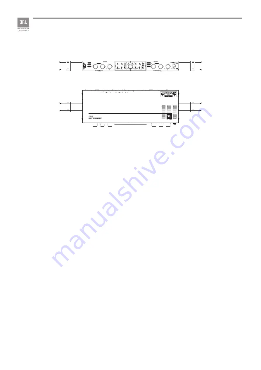
To install the mixer, you can use one of the following approaches:
•
Use the original brackets come with the mixer.
1. Align holes of a bracket with the holes on the case.
2. Fasten the bracket with the provided screws.
3. Follow step 1 to 2 to install rest bracket(s) to the case according your application.
4. Install the assembly into the cabinet. For details of installation in the chassis of the cabinet, refer to
the user guide of your cabinet.
•
Install the mixer to the wall. See the Method 2 in the above figure.
•
Stack amps without using a cabinet.
NOTE
: When transporting, the mixer should be supported at both front and back.
Method 1 - Attaching the brackets to the front panel for rack mounting
Method 2 - Attaching the brackets to the sides of the unit for wall mounting
Summary of Contents for JBL CSM-21
Page 1: ...CSM 21 CSM 32 Mixer User Guide Commercial Solutions Series...
Page 2: ......
Page 3: ...CSM 21 CSM 32 User Guide...
Page 25: ...21 Appendix C Block Diagrams...
Page 29: ...CSM 21 CSM 32...
Page 32: ...2 E N L L N E 3MM 240V CSA UL...
Page 36: ...6 2 0 2 1 2 2 1U 2 3 1 2 3 1 2 4...
Page 40: ...10 13 Priority Hold SOURCE 1 SOURCE 2 SOURCE 3 14 MIC 15 48V...
Page 46: ...16 6 8 LevalGuard LevelGuard 12 LevelGuard LED LevelGuard LED 6 9...
Page 48: ...18 B CH1 CD Source CSR 2SV CSM 21 CSPM 1 CSA 2120 CST 2120 PC Source CSM LevelGuard AutoWarmth...
Page 51: ...21 C...
Page 55: ...25 Pb Hg Cd Cr 6 PBB PBDE SJ T11363 2006 X SJ T11363 2006 F RoHS...


