background image

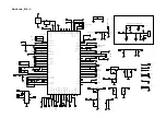
Mic Circuit(Close To BT Modle Circuit)

Main Board_BT & IO

R217

0R

R216

NC

R82

2.2K

C85

15P

C84

104P

L5

15nH/300mA

R80

1K

C81

106P

C13

103P

C86

39P

ESD2

150TA

1

2

J3

TP

1

8

TP20

1

GPIO4/UART0_CTS

2

GPIO1/UAR0_TX

3

GPIO2/UART0_RTS

4

GND0

5

VDD_FEM

6

BOOT_SEL

7

GPIO7/PROM_SCL

8

GPIO8/PROM_SDA

9

GND1

10

GPIO16/I2S0_LR

11

GPIO17/I2S0_DI

12

GPIO15/I2S0_SCLK

13

GPIO18/I2S0_DO

14

VBAT

15

VCHG

16

GND2

17

VDD33

18

PWR

19

RST

20

GPIO_L_13/LCD_D5

21

GPIO_L_4/LCD_CSB

22

AIO

23

GPIO_L_14/LCD_D6

24 GPIO_L_11/LCD_D3

25

GPIO_L_15/LCD_D7

26

GPIO_L_5/LCD_DO[D1]

27

GPIO_L_12/LCD_D4

28

GPIO_L_10/LCD_D2

29

GPIO_L_9/LCD_RDN

30

GPIO13_UART1_TX

31

GPIO14/UART1_RX

32

GPIO_L_7/LCD_CLK[D0]

33

GPIO_L_6/LCD_A0

34

GPIO_L_8/LCD_WRN

35

GPIO9/SPI_CSB

36

FLASH_CS

37

GPIO10/SPI_DI

38

GPIO_L_1/SPI_WPB

39

GPIO_L_0/SPI_HOLDB

40

GPIO12/SPI_CLK

41

GPIO11/SPI_DO

42

HPOUTLP

43

HPOUTLN

44

HPOUTRP

45

HPOUTRN

46

AGND

47

MBIAS

48

MICLP

49

MICLN

50

MICRP

51

MICRN

52

GND3

53

USBVCCA33

54

USB_ID

55

USB_DP

56

USB_DN

57

USB_VBUS

58

GPIO_L_2/SD_DETECT

59

GPIO19/I2S1_SCLK

60

GPIO22/I2S1_DO

61

GPIO21/I2S1_DI

62

GPIO20/I2S1_LR

63

GND4

64

GPIO6/SWDIO

65

GPIO_L_3/VBS_DRV

66

GPIO_L_16/SD_LOCK

67

GPIO5/SWCLK

72

SD_DATA1

73

SD_SLK

74

GND5

75

RFOUTANT

76

GND6

77

GPIO3/UART0_RX

68

SD_DATA2

69

SD_CMD

70

SD_DATA3

71

SD_DATA0

U10

MODULE-JX265-01-V1.3

R81

0

C14

NC

C15

NC

R158

0R

R164

NC

ESD10

150TA

C96

106P

R97

NC

R94

0R

R98

0R

R99

NC

C95

105P

R102

NC

R157

NC

R163

10K

R107

0R

C94

225P

R161

0R

C91

105P

C93

5pF

C92

5pF

1

2

3

RF1

RFCON

TP50

TP46

TP49

TP56

TP57

TP54

TP51

R162

130K

R160

NC

C90

104P

C89

475P

R156

0R

Q1

NC

R152

NC

R78

NC

Q9

NC

R155

NC

R142

NC

C155

33P

C88

104P

C87

106P

C139
104P

ESD9

150TA

C138

104P

ESD7

150TA

3

1

2

Q5

2N3906

Q6

2N3904

R106

100K

R109

10K

R114

100K

R113

47K

R112

10K

R115

4.7K

R116

4.7K

C98

5p

C97

5pF

TP3

TP16

TP19

TP21

TP22

TP23

TP24

TP25

TP

2

7

TP28

TP29

TP31

TP32

TP33

TP34

TP

3

5

TP

4

2

TP

4

3

C119

104P

C120

106P

FB2

1K@100M

R39

10K

Q12

2N3904

R45

10K

R50

4.7

C31

104P

R96

1K

MIC_IN

MIC_BIAS

AMP_MUTE

SWCLK

SWDIO

SYS_3V3

KEY_LINK

VDD_FEM

BOOT_SEL

FEM_LDO_EN

KEY_PLAY

KEY_BT

KEY_VOL-

BAT_DET

USB_5V

SYS_3V5

VDD33

PWR

VREG_EN

REST

INT

/SHDN

POWER_OFF_READY

GPIO_L11

SYS_3V3

SYS_3V3

I2C_SCL

DE

T

E

CT

5V

_

2

.3

A

GPIO_L10

CONTROL_14V

GPIO13

GPIO14

I2C_SDA

GPIO9

FLASH_CS

GPIO11

BT_R+

BT_R-

MIC_BIAS

MIC_IN

NTC2

USBVCCA33

USB_DM

USB_DP

USB_5V

IO_INT

POWER_ON_OFF

VCHG

GPIO_L10

VCHG

BOOT_SEL

GPIO13

SYS_3V3

VDD33

NTC2

SYS_3V3

FEM_LDO_EN

VDD_FEM

BOOT_SEL

PWR

SYS_3V3

USBVCCA33

USB_5V

INT

I2C_SDA

I2C_SCL

SYS_3V3

DC_DET_BT

AMP_SDZ

BOOST_EN

AIO

BAT_DET

POWER_LED_CONTROL

POWER_LED_CONTROL

POWER_W_LED

GPIO_20

Summary of Contents for JBL FLIP 5

Page 1: ...29 Spare Parts List 30 Revision List 32 FLIP 5 S N Starting from CS SKU JBLFLIP5BLK JBLFLIP5BLU JBLFLIP5RED JBLFLIP5GRY JBLFLIP5TEAL JBLFLIP5WHT JBLFLIP5GREN JBLFLIP5YEL JBLFLIP5PINK JBLFLIP5SAND JBLFLIP5BLKAM JBLFLIP5BLUAM JBLFLIP5REDAM JBLFLIP5GRYAM JBLFLIP5TEALAM JBLFLIP5WHTAM JBLFLIP5GRENAM JBLFLIP5YELAM JBLFLIP5PINKAM JBLFLIP5SANDAM Released by Global Quality harman kardon Inc 8500 Balboa Blv...

Page 2: ...hium ion polymer 17 3WH Equivalent to 3 6V 4800MAH Battery charge time 2 5 hours 5V 2 3A Frequency response 60Hz 20kHz Music playtime Up to 12 hours Varies by volume level and audio content Bluetooth transmitter power 0 20DBM Bluetooth transmitter frequency range 2 402 2 480GHZ Bluetooth transmitter modulation GFSK π 4 DQPSK 8DPSK Dimensions W D H 181 x 69 x 74 mm Weight 538g ...

Page 3: ...no guarantee that interference will not occur in a particular installation If this equipment does cause interference to radio or television reception which can be determined by turning the equipment off and then on the user is encouraged to try to correct the interference by one or more of the following measures Increase the separation between the equipment and receiver Connect the equipment to a ...

Page 4: ...can generate electrical change sufficient to damage ES devices 6 Do not remove a replacement ES device from its protective package until immediately before you are ready to install it Most replacement ES devices are packaged with leads electrically shorted together by conductive foam aluminum foil or comparable conductive material 7 Immediately before removing the protective material from the lead...

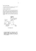
Page 5: ...screwheads metal overlays control shaft etc Plug the AC line cord of the appliance directly into a 120V AC 60Hz outlet and turn the AC power switch on Any current measured must not exceed o 5mA Device under test Test all exposed metal surfaces Also test with plug reversed Using AC adapter plug as required Leakage current tester Reading should not be above 0 5mA Earth ground AC Leakage Test ANY MEA...

Page 6: ...ault in On Mode Volume Bluetooth Long press 10s Enter by pass mode in On Mode Volume Phone Long press 10s Enter Regular DFU mode in On Mode Volume Link Long press 2s Show SW version in On Mode Volume Link Long press 10s Enter Demo mode in On Mode Remark all combination function shall triggered by long pressing Table 4 Combination button for debug and factory test ...

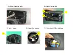
Page 7: ...1 Take out the graphic carton Disassembly Instructions 2 Take out the inner box 3 Open the inner box 4 Take out the product 5 Remove the grille 6 Remove wrapping housing ...

Page 8: ...3 2 9 Remove 4 screws as shown 10 Take out the driver 1 4 3 2 4 7 Remove screw as shown and take out the metal ring and recess 1 8 Take off PR for both side 1 ...

Page 9: ...15 Pull out main PCBA and battery 12 Unplug 3 connectors 2 1 3 1 1 11 Pull out the driver cable 13 Tear off antenna 14 Unplug Mic connector ...

Page 10: ... 2 screws and take out Key PCBA b 4 2 18 Unscrew below 2 screws and take out LED PCBA c 6 3 a 17 a Take out Type C socket b Teal off volume silicone button c Teal off power silicone button 5 1 16 Unscrew below 6 screws ...

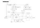
Page 11: ...V_SLG4V4 DCDC_BIAS VCC_ 3 3V_BT IO VCC_ 3 3V_OP 3 3V_SLG4V4 VCC_ 3 3V_OP PowerButton Logic SLG46140 OP TP2412 AMP_5 2V 14V DCDC_BIAS ANT BAT_3 8V I2C 128MHz Analogsignal TypeCUSBport Upgrade BTMODULE JX265 Q1 Mute AMP TPA3128D2 3ohm 20W Analog I2C VCC_ 3 3V_BT IO ButtonS MIC I OExpander LEDs AW9110 HMM JBL Flip5 Block Diagram ...

Page 12: ...Speaker Red 3 ohm Black Main Board Battery Led key board Key Board USB Board MIC ANT Flip5 Wiring Diagram ...

Page 13: ...ND5 75 RFOUTANT 76 GND6 77 GPIO3 UART0_RX 68 SD_DATA2 69 SD_CMD 70 SD_DATA3 71 SD_DATA0 U10 MODULE JX265 01 V1 3 R81 0 C14 NC C15 NC R158 0R R164 NC ESD10 150TA C96 106P R97 NC R94 0R R98 0R R99 NC C95 105P R102 NC R157 NC R163 10K R107 0R C94 225P R161 0R C91 105P C93 5pF C92 5pF 1 2 3 RF1 RFCON TP50 TP46 TP49 TP56 TP57 TP54 TP51 R162 130K R160 NC C90 104P C89 475P R156 0R Q1 NC R152 NC R78 NC Q9...

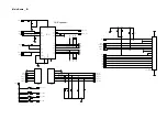
Page 14: ... R36 100K C45 105P C46 475P RT1 8 66K RT2 130K L2 1uH RS1 10MR C48 104P TP5 TP6 1 2 3 4 BAT CON4P 1 IN 2 V 3 IN 4 OUT 5 V U13 LMV331TP R183 NC R184 39 2K R185 51K C157 104P C158 105P R188 47K C160 474P R192 0R R194 10K R186 1K FB1 30 3A C18 104P RT3 20R RT5 11k C21 104p USB_5V INT I2C_SCL I2C_SDA NTC1 BAT BAT NTC1 NTC2 USB_DM USB_5V DETECT5V_2 3A USB_DP SYS_3V3 Main Board_Charge ...

Page 15: ... 5uH C26 104P R19 1K C27 475P R20 NC R21 NC C28 224P R22 1K R23 18K C29 472P C30 103P R24 15K C33 106P C34 104P C35 103P R25 470K R26 15K R28 120K R29 0R R30 47K 1 S 2 S 3 S 4 G 5 D 6 D 7 D 8 D U44 ME4435 C36 104P R31 100K R32 1K R33 100K R34 10K C37 104P TP2 C166 220uF 25V Q2 2N3904 R91 4R7 C38 2 2nF BAT BOOST_EN 13V DC_BIAS 13V PVCC BOOST_EN Main Board _ Power ...

Page 16: ...2 TP TP TP 1 2 SPK R108 10R R1 10R R2 NC R3 NC R4 56R R43 56R R5 NC R8 1K R9 47K R10 NC R12 10K R11 100K C163 225P C12 225 C2 330P C56 104P C57 106P C6 684P C7 104P C9 102P C8 332P C65 332P C5 102P C80 104P C82 684P C3 NC C4 NC C1 330P C77 104P C78 106P C71 224P C68 224P C67 224P C62 224P C10 104P C11 105P R16 5 6K 1 R6 NC 1 C165 Q7 2N3904 TP TP TP TP R51 NC C41 150P R86 0R R87 0R R89 1K 1 R100 NC...

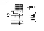
Page 17: ...W3 VOL R130 10K SW4 LINK R133 10K ESD5 150TA ESD6 150TA ESD11 150TA 1 2 3 4 5 6 CN6 CON6P 1 2 3 4 5 6 CN5 CON6P ESD15 150TA ESD16 150TA ESD17 150TA FB3 1k 100m 1 2 3 4 5 6 7 8 9 10 11 12 13 14 15 16 17 CN1 CN 15PN 2PAD ESD12 150TA 1 2 C32 105P SYS_3V3 I2C_SCL I2C_SDA SHDN SYS_3V3 IO_INT SYS_3V3 LED1 LED2 LED3 LED4 LED5 LED6 BT_W_LED RING_W_LED KEY_BT BT_W_LED POWER_W_LED RING_W_LED POWER_KEY SYS_3...

Page 18: ...A LED6 RED K A LED7 WHITE K A LED9 WHITE K A LED10 WHITE K A LED11 WHITE K A LED13 WHITE K A LED14 WHITE R103 200R K A LED15 WHITE R110 200R K A LED16 WHITE 1 2 3 4 5 6 7 8 9 10 11 12 13 14 15 16 17 CN7 CN 15PN 2PAD R15 200R K A LED17 WHITE R27 200R K A LED18 WHITE SYS_3V3_1 SYS_3V3 KEY_BT1 POWER_KEY1 KEY_BT1 BT_W_LED1 POWER_W_LED1 RING_W_LED1 POWER_KEY1 SYS_3V3_1 LED6_1 LED5_1 LED4_1 LED3_1 LED2_...

Page 19: ... XP2 12 GND 13 GND 14 XP1 15 XN1 16 VBUS 17 SBU2 18 DN2 19 DP2 20 CC2 21 VBUS 22 XN2 23 XP2 24 GND XP1 TYPE_C UT1117 R7 22K R79 33K C164 102P R37 NC R38 NC C19 NC FB6 22R FB4 22R R93 470K 1 R95 nc 1 USB_5V USB_DM USB_DP TYPE_C_5V TYPE_C_5V TYPE_C_USB_DP TYPE_C_USB_DM TYPE_C_USB_DP TYPE_C_USB_DM USB_5V DC_DET_BT CC1 USB_5V 5V_DET_SL USB_5V USB_DP1 USB_DM1 BAT_DET AIO USB Board _ IO ...

Page 20: ... 2 D2 IN4148 C55 475P C58 104P R63 100K C59 106P R64 1M R65 510K R66 0R R67 10K C60 475P 1 2 D1 IN4148 C61 475P C63 104P R68 1K R69 1K C69 475P C70 104P C72 475P C73 475P R70 30K R71 30K C74 NC C75 NC R72 15K C76 47P R73 22K R74 22K C113 106P C114 104P C115 102P C116 102P R75 15K C117 47P C118 475P R76 0R R77 NC R149 4R7 TP15 R187 10k R189 100K C161 104P Q8 2N3904 R49 10K R14 NC 3K C17 102P A VREG...

Page 21: ...D 3 CE 4 NC 5 VOUT U12 LP3984H 33B5F C136 104P C137 103P R148 10K C140 104P C141 103P C142 106P C143 104P S G D Q10 ME2345A S G D Q11 ME2345A C146 104P R178 100k R179 47k C148 104P R180 100k R181 4 7k 1 2 D3 IN5819 D4 IN5819 R182 10R C154 104P C156 105P FB5 1K 100M Q3 2N3904 C16 105P 1 FB 2 IN 3 GND 4 OUT 5 LX 6 EN U14 R40 18K R41 1 1K R85 2 2R R90 0R R92 0 1R C40 102P 1 2 D7 NC 1 2 D5 NC VCC_SLG4...

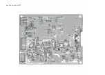
Page 22: ...Main PCB_TOP LAYOUT ...

Page 23: ... Main PCB_BOTTOM LAYOUT ...

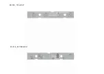
Page 24: ...KEY PCB _ TOP LAYOUT m GND KEY PCB _ BOTTOM LAYOUT ...

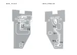
Page 25: ... LED PCB _ TOP LAYOUT LED PCB _ BOTTOM LAYOUT ...

Page 26: ...USB PCB _ TOP LAYOUT TP3 USB PCB _ BOTTOM LAYOUT ...

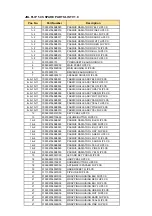
Page 27: ...IATOR L WHT FLIP5 CS 14 2 1003047565B0027 PASSIVE RADIATOR L SAND FLIP5 CS 14 2 1003047565B0028 PASSIVE RADIATOR L TEAL FLIP5 CS 14 2 1003047565B0029 PASSIVE RADIATOR L PINK FLIP5 CS 14 2 1003047565B0030 PASSIVE RADIATOR L YEL FLIP5 CS 15 200609220007C00 LED AND KEY PCBA FLIP5 CS 16 200608220013C00 USB PCBA FLIP5 CS 17 300799000174E01 RUBBER BUTTON FLIP5 CS 18 309999000022C00 ASTIGMATIC PAPAER FLI...

Page 28: ...ASSY TEAL FLIP5 CS 8 9 10 11 1003047565B0009 FABRIC GRILLE ASSY PINK FLIP5 CS 8 9 10 11 1003047565B0010 FABRIC GRILLE ASSY YEL FLIP5 CS 12 200607220012C00 KEY PCBA FLIP5 CS 13 300799000176E00 VOLUME BUTTON FLIP5 CS 14 2 1003047565B0021 PASSIVE RADIATOR L BLK FLIP5 CS 14 2 1003047565B0022 PASSIVE RADIATOR L RED FLIP5 CS 14 2 1003047565B0023 PASSIVE RADIATOR L BLU FLIP5 CS 14 2 1003047565B0024 PASSI...

Page 29: ...D00 STRAP YEL FLIP5 CS 309908000075D00 STRAP PINK FLIP5 CS 309908000074D00 STRAP TEAL FLIP5 CS 309908000073D00 STRAP SAND FLIP5 CS 309908000072D00 STRAP WHT FLIP5 CS 309908000071D00 STRAP GREN FLIP5 CS 309908000070D00 STRAP GRY FLIP5 CS 309908000069D00 STRAP BLU FLIP5 CS 309908000068D00 STRAP RED FLIP5 CS 309908000067D00 STRAP BLK FLIP5 CS 300401990043D00 EPP CASE FLIP5 CS 300403110282D00 GIFT BOX...

Page 30: ...Revision List Version 1 0 Initial release for JBL Flip 5 2019 4 ...

Reviews: