12
12
TROUBLESHOOTING
If your amplifier isn't performing the way you think is should, check to see if the problem is covered in this section before calling your dealer or
contacting JBL customer service.
PROBLEM
CAUSES AND SOLUTIONS
No sound (the amplifier's Power LED is off)
• Check that the amplifier's +12V and GND connections have been properly made.
• Check if the fuse on the +12V wire located near the battery is blown: If so, replace it with an
identical fuse.
• Check all amplifier fuses; if any are blown, replace them with identical fuses.
• If you are using the amplifier's REM connection for turn-on, check that the wire is properly
connected to the audio system's remote turn-on wire or to the vehicle's ACC power terminal.
No sound (the amplifier's Power LED is orange)
• Check that all amplifier input and speaker connections have been properly made.
• Check that the amplifier's Level controls are not turned all the way down (counter-clockwise).
• Check that the vehicle audio system's source unit's volume control is not turned all the way
down.
No sound (the amplifier's Protection LED is red)
• Confirm that the vehicle's electrical system is supplying between 9V and 16V DC to the
amplifier. If the supply voltage is outside of this range, correct the condition before attempting
to use the amplifier.
• If the amplifier has overheated, wait until it has cooled down before attempting to use it again.
• Disconnect all speakers from the amplifier and attempt to turn it on again:
– If the amplifier turns on (the Power LED is orange), there is a short circuit in one or more of
the speaker wires. Correct all short circuits before reconnecting the speakers to the amplifier.
– If the amplifier does not turn on (the Protection LED is still red and the Power LED is off),
contact your authorized JBL dealer for assistance.
Summary of Contents for JBL GX-A422SI
Page 2: ...GX A422SI power amplifier OWNER S MANUAL...
Page 17: ...1 GX A422SI 4 2 2 channel or...
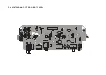
Page 22: ...PCB LAYOUT DIAGRAM FRONT END BOARD TOP VIEW...
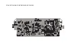
Page 23: ...PCB LAYOUT DIAGRAM FRONT END BOARD BOTTOM VIEW...
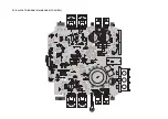
Page 24: ...PCB LAYOUT DIAGRAM MAIN BOARD TOP VIEW...


