background image

7

INTRODUCTION

Thank you for purchasing a Soundcraft MPMi/MFXi mixer. The MPMi and MFXi ranges 
are our most cost-effective mixing solutions, bringing you all the features and per-
formance that you expect from a Soundcraft product, at an extraordinarily low price.
The packaging, in which your console arrived, forms part of the product and must 
be retained for future use.
Owning a Soundcraft console brings you the expertise and support of one of the 
industry’s leading manufacturers, and the results of over three decades of support-
ing some of the biggest names in the business. Our knowledge has been attained 
through working in close contact with leading professionals and institutes to bring 
you products designed to get the best possible results from your mixing.
Built to the highest standards using quality components and surface mount technol-
ogy, the MPMi/MFXi is designed to be as easy to use as possible. We have spent 
years researching the most efficient methods of control for two key reasons:
1) Engineers, musicians, writers and programmers all need to have very few inter-
ruptions to the creative process; our products have been designed to be almost 
transparent, allowing this process to breathe.
2) Whether performing or recording, time is a very expensive and rare commodity. 
Our products have a user interface which is recognised by millions to be the industry 
standard because of its efficiency.
The sonic qualities of our products are exemplary - some of the same circuits which 
are used on our most expensive consoles are employed in the MPMi/MFXi, bringing 
you the great Soundcraft quality in a small format console without compromise.
You will also be glad to know you have a one year warranty with your product from 
the date of purchase.  The MPMi/MFXi has been designed using the latest high-end 
software based engineering packages.  Every console from Soundcraft has been 
proven to stand up to all the stress and rigours of modern day mixing environments.
The entire MPMi/MFXi range is manufactured using some of the most advanced 
techniques in the world, from high density surface mount PCB technology, to com-
puter aided test equipment able to measure signals well outside the range of normal 
hearing.  As each console passes through to be quality checked before packing, 
there is also a human listening station. Something we have learnt over the years is 
that the human touch counts - and only by using people can you ensure the product 
meets the high demands of the user.

ADVICE FOR THOSE WHO PUSH THE BOUNDARIES

Although your new console will not output any sound until you feed it signals, it has 
the capability to produce sounds which when monitored through an amplifier or 
headphones can damage hearing over time.
Please take care when working with your audio - if you are manipulating controls 
which you don’t understand (which we all do when we are learning), make sure your 
monitors are turned down. Remember that your ears are the most important tool of 
your trade, look after them, and they will look after you.
Most importantly - don’t be afraid to experiment to find out how each parameter 
affects the sound  -  this will extend your creativity and help you to get the best from 
your mixer and the most respect from your artists and audience.

Summary of Contents for MFXi

Page 1: ...1 USER GUIDE...

Page 2: ...from the use of information or any error contained in this manual No part of this manual may be reproduced stored in a retrieval system or trans mitted in any form or by any means electronic electrica...

Page 3: ...ER SECTION 24 Lexicon FX PROCESSOR OVERVIEW MFXi only 28 FX OPERATION 29 FX PROCESSOR CONTROLS 30 REVERBS 31 REVERB CONTROLS 32 DELAYS 33 DELAY CONTROLS 33 MODULATED EFFECTS 34 FACTORY RESET 36 EFFECT...

Page 4: ...nly use attachments accessories specified by the manufacturer Use only with the cart stand tripod bracket or table specified by the manufacturer or sold with the apparatus When a cart is used use caut...

Page 5: ...bol The wire which is coloured Blue must be connected to the terminal in the plug which is marked with the letter N The wire which is coloured Brown must be connected to the terminal in the plug which...

Page 6: ...hin the product s enclosure that may be of suf ficient magnitude to constitute a risk of electric shock to persons CAUTIONS The exclamation point within an equilateral triangle is in tended to alert t...

Page 7: ...les are employed in the MPMi MFXi bringing you the great Soundcraft quality in a small format console without compromise You will also be glad to know you have a one year warranty with your product fr...

Page 8: ...0 10 0 10 0 10 0 10 0 10 0 10 0 10 L L L L L L L L L L L L L L L R R R R R R R R R R R R R R R 3 3 6 6 9 9 12 12 15 15 0 3 3 6 6 9 9 12 12 15 15 0 3 3 6 6 9 9 12 12 15 15 0 3 3 6 6 9 9 12 12 15 15 0...

Page 9: ...ntrols set the output levels of the two Aux Outputs The After Fade AFL SWITCHES AFL Listen switches route their respective aux output signal to the monitor headphones outputs 28 AUX 2 POST PRE SWITCH...

Page 10: ...0 10 0 10 0 10 0 10 0 10 0 10 0 10 0 10 0 10 0 10 0 10 0 10 0 10 0 10 0 10 0 10 0 10 0 10 0 10 0 10 0 10 0 10 0 10 0 10 0 10 0 10 0 10 0 10 0 10 0 10 0 10 0 10 0 10 0 10 0 10 0 10 0 10 0 10 0 10 0 10...

Page 11: ...adphones impedance is 32 ohms or greater 25 AUX 1 2 3 OUTPUTS These outputs can be used to send the channel signal to an artist s monitors Jacks headphones in ear stage monitors external FX or seconda...

Page 12: ...wn although you should then keep cable lengths as short as possible to minimise inter ference pick up on the cable Note that the ring must be grounded if the source is unbalanced Set the input level u...

Page 13: ...urces can be fed to both paths by plugging into the Left jack only Mix Outputs The MIX outputs are on XLR s wired as shown and incorporate impedance balancing allowing long cable runs to balanced ampl...

Page 14: ...nd only at their source and not at both ends If the use of unbalanced connections is unavoidable you can minimise noise by following these wiring guidelines On INPUTS unbalance at the source and use a...

Page 15: ...nt outputs or to auxiliary sends to identify problems on the Master section Compare a suspect channel with an adjacent channel which has been set up identically Use PFL to monitor the signal in each s...

Page 16: ...TEREO H PHONES HEADPHONES LEVEL MONITOR OUT LEVEL BALANCE FADER PK STEREO CHANNEL STEREO 1 2 IDENTICAL LEFT MONO RIGHT GAIN POST FADER SIGNAL d c PFL MUTE PRE FADER SIGNAL POST FADER SIGNAL 15dB MIX O...

Page 17: ...LEFT MIX RIGHT MONITOR OUT L MIX R OUT SOLO METERS L R 16 10 6 3 0 3 6 16 22 MONITOR METERS STEREO H PHONES HEADPHONES LEVEL MONITOR OUT LEVEL BALANCE FADER PK STEREO CHANNEL STEREO 1 2 IDENTICAL LEF...

Page 18: ...4 jacks Use this input for sources other than mics such as keyboards drum machines synths tape machines or DI d guitars The input is BALANCED for low noise and top quality from professional equipment...

Page 19: ...o 15dB reducing hiss or excessive sibilance which can occur with certain types of microphone Set the knob in the centre detented position when not required MID EQ There are two knobs which work togeth...

Page 20: ...hing PFL switch is pressed the pre fade pre mute signal is fed to the headphones control room output and meters where it replaces the MIX The SOLO LED on the Master section illuminates to warn that a...

Page 21: ...iving 15dB of boost or cut at 12kHz MF EQ Turn to the right to boost mid frequencies by up to 15dB turn to the left to cut these frequencies by up to 15dB The centre frquency of the MF EQ is 720Hz LF...

Page 22: ...e input level is set correctly to give maximum travel on the fader which should normally be used at around the 0 mark See the Initial Setup section on page 33 for help in setting the right level 9 PFL...

Page 23: ...23...

Page 24: ...10 6 3 0 3 6 12 16 22 MIX SOLO PHANTOM POWER LEVEL AUX1 OUT AUX2 OUT FX BUS OUT MONO OUT 2TRK SUB TO MIX MNTR LEVEL LEVEL STE MNO MIX SUB 5 10 0 5 10 20 30 5 10 0 5 10 20 30 MUTE FX 48V HEADPHONES SU...

Page 25: ...0 10 POST PRE 48V L L R R REC OUT 2TRK IN LEVEL 0 10 0 10 0 10 0 10 0 10 TO MNTR TO MIX MIX L MIX R 16 10 6 3 0 3 6 12 16 22 MIX SOLO PHANTOM POWER 2TRK SUB TO MIX MNTR LEVEL LEVEL STE MNO MIX SUB 5 1...

Page 26: ...ft and Right line level inputs used for connecting a playback device 4 2 TRACK LEVEL CONTROL This adjusts the signal level from the 2 Track inputs 5 2 TRACK TO MIX Press this switch to route the 2 Tra...

Page 27: ...se to the 0 mark if the input GAIN settings have been correctly set to give maximum travel on the faders for smoothest control 15 SUB TO MIX This switch routes the Sub L and Sub R signals to the main...

Page 28: ...ces the MIX The SOLO LED on the Master section illuminates to warn that an AFL is active 27 FX BUS OUTPUT This output carries the signal from the FX bus It could be used as a third Aux Output if desir...

Page 29: ...that the console has 32 programs which are held in two banks of 16 programs There are individual BANK A and BANK B LED s to indicate which bank is cur rently active When turning the rotary Program Sel...

Page 30: ...FX processor is muted There is a handy aide memoir of the programs printed on the front panel 7 Clip LED This LED illuminates when either the incoming audio or the proc essed audio within the effect...

Page 31: ...everb A Plate reverb is a large thin sheet of metal suspended upright under tension on springs Transducers attached to the plate transmit a signal that makes the plate vibrate causing sounds to appear...

Page 32: ...her acting as a microphone connected by a simple set of springs The characteristic boing of a spring is an important component of many classic rock and rockabilly guitar sounds REVERB CONTROLS Pre Del...

Page 33: ...the tape moving in the space between the record and playback heads while delay time was adjusted by changing the speed of the tape loop Although very musical sounding wow and flutter combined with a s...

Page 34: ...ond tap occurs later than they did at the 12 o clock position When the knob is turned clockwise the first tap occurs later and the second tap occurs earlier Depth This controls the intensity of modula...

Page 35: ...Knob 1 Speed Controls the modulation rate of the Tremolo Panner Knob 2 Depth Controls the intensity of the volume amplitude change Knob 3 Phase Controls whether the amplitude change occurs in both ch...

Page 36: ...nd right channel waveforms out of phase resulting in a left to right panning motion This effect shifts the frequency spectrum of the input signal Altering the pitch of a sound produces a wide range ef...

Page 37: ...37 EFFECTS DATA CHART Note H repeat hold function see page 29 2nd paragraph...

Page 38: ...dB MF swept 150Hz 3 5kHz 15dB LF 80Hz 15dB Q MF 1 5 EQ Stereo inputs HF 12kHz 15dB MF 720Hz 15dB LF 80Hz 15dB Q MF 0 8 Power Consumption Less than 40W Operating Conditions Temperature Range 5 C to 40...

Page 39: ...39...

Page 40: ...ion of unwanted sounds and elimination of feedback is important The aim should be to place the microphone as close as physically possible to the source to cut out unwanted surround ing sounds allow a...

Page 41: ...ember that the mixer is a mixer not an amplifier Increasing the overall level is the job of the amplifier and if it is impossible to provide adequate level it is probable that the amplifier is too sma...

Page 42: ...5 10 0 5 10 20 30 5 10 0 5 10 20 30 A DECAY B FBK DPTH MUTE FX 10 20dB 10 20dB 48V HEADPHONES 10 10 10 10 10 10 10 10 10 10 EFFECTS STE1 STE2 SUB L SUB R MIX X MF LINE LINE LINE LINE LINE LINE LINE LI...

Page 43: ...10 0 10 0 10 0 10 0 10 0 10 0 10 0 10 0 10 0 10 0 10 0 10 0 10 0 10 0 10 0 10 0 10 0 10 0 10 0 10 0 10 0 10 0 10 0 10 0 10 0 10 0 10 0 10 0 10 0 10 0 10 0 10 0 10 0 10 0 10 0 10 L L L L L L L L L L L...

Page 44: ...later date WARNING ensure that the mixer is disconnected from the mains supply and all other equipment before fitting the rack mounting brackets A and remove the side mouldings Undo and remove the sc...

Page 45: ...A Attach captive rack nuts at points 1 B Attach rack bolts through points 2 and into fitted rack nuts at points A The console can now be fitted to a standard 19 rack Note the extender can be fitted to...

Page 46: ...L R R REC OUT 2TRK IN STEREO 1 STEREO 2 STEREO RETURN L L SUB R R L L L R R R MONO MONO MONO MIX L MIX R PHANTOM POWER AUX1 OUT AUX2 OUT FX BUS OUT MONO OUT MUTE FX HEADPHONES 32 Ohms GRAPHIC EQ STAGE...

Page 47: ...STEREO RETURN L L SUB R R L L L R R R MONO MONO MONO MIX L MIX R PHANTOM POWER AUX1 OUT AUX2 OUT FX BUS OUT MONO OUT MUTE FX L L R R 2TRK INSTRUMENT AND VOCAL SOURCES FILL AMPLIFIER GRAPHIC EQ MONITOR...

Page 48: ...X INSTRUMENT AND VOCAL SOURCES GRAPHIC EQ AMPLIFIER FOLDBACK INDUCTION LOOP INDUCTION LOOP AMP CD PLAYER GRAPHIC EQ AMPLIFIER MAIN PA LEFT AND RIGHT HEADPHONES 32 Ohms CASSETTE OR DAT MACHINE APPLICAT...

Page 49: ...ANTOM POWER AUX1 OUT AUX2 OUT FX BUS OUT MONO OUT MUTE FX SPEAKER SWITCH AMPLIFIER PASSIVE MONITORS ACTIVE MONITORS INSTRUMENT AND VOCAL SOURCES CONTROL ROOM STUDIO GRAPHIC EQ AMPLIFIER ARTIST S FOLDB...

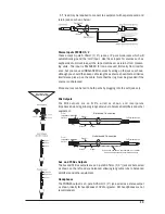
Page 50: ...50 TYPICAL CONNECTING LEADS...

Page 51: ...leeve 3 3 Sleeve Sleeve 3 Sleeve Sleeve Sleeve Sleeve Sleeve Sleeve Sleeve Sleeve TIP TIP TIP TIP TIP TIP TIP TIP TIP TIP TIP TIP TIP TIP TIP TIP TIP RING RING RING RING RING RING RING RING RING RING...

Page 52: ...A feed sent back to the artistes via loudspeakers or headphones to enable them to monitor the sounds they are producing Frequency response The variation in gain of a device with frequency Gain The amo...

Page 53: ...or below the break frequency i e a highpass or lowpass derived response Solo An almost generic term used to describe PFL or AFL functions Spill Acoustic interference from other sources Transient A mo...

Page 54: ...o and from the Dealer or Soundcraft and postage must be prepaid 4 This warranty shall only be valid if a the Equipment has been properly installed in accordance with instructions contained in Soundcra...

Reviews: