background image

Oakleaf Woodburning Stove

Dry Seasoned Wood Only!

Harman®  •  Oakleaf Owner's Manual_R23  •  2010 -___  •  09/15

12

3-90-798

C. Floor Protection Requirements

Floor Protection Requirements

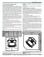
If the Oakleaf is being installed on a combustible floor, the 

bottom heat shield (part # 1-00-797058) must be installed 

with  a  suitable  material  for  floor  protection.  (See  Section 

7F). This heat shield is supplied with the unit and must be 

installed. Floor protection must be at least 3/8 "(9.5 mm) thick 

insulating material having a value equal to or greater than 

0.84k/in. (The higher the value of k, the better the protection.)
Another method for calculating floor protection is in R value. 

This requirement would be for an R value of 0.89 or higher. 

(The higher the R value, the better the protection).
In all installations, the area under and around the stove must 

be protected from falling ash and live coals. 

The area under a 

horizontal run of chimney connector must also be protected, 

extending two (2) inches beyond the measurement of the 

horizontal connector.


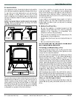
Further guidelines for floor protection are as follows: 
In the U.S. the floor protector must be completely under the 

stove, and extending 18" in front of the door opening, 8" to 

each side and 8" to the back.
In Canada, the floor protection must extend 18" (457mm) 

in front of the door opening, 8" (203mm) to each side and 

extend to the wall behind the stove.
Minimum Size floor protection (USA) is 42-3/4" Deep by 32-

5/8" Wide.
Floor protection touching the wall: 53-3/8" Deep x 32-5/8" 

Wide.

DANGER: 

The  appliance  legs  may  not  be  removed  for 

installation.
Minimum Size floor protection (USA) is 32-5/16" Wide By 

43-3/8" Deep.

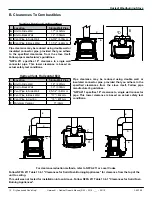
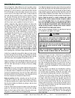
Parallel versus Corner Installations

A parallel installation is one in which the back and sides of 

the stove are parallel to the walls behind and to the side of 

the stove. A corner installation is one in which the back of the 

stove is positioned diagonally across a corner of the room. 

Each installation requires its own set of clearances.

For  corner  installations,  the  required  clearance  distances 

from the stove are:
1. to the side wall, 14" (356mm).

2. From the flue connector to the wall, 21-3/4" (552mm)

3. Horizontal pipe to the ceiling, 16" (406mm). 
For a vertical chimney connector in a parallel installation the 

distance of the connector to the side wall must be 26-3/4" 

(679mm), due to the required side clearance of the stove 

itself. Fireplace installations must meet these same clearance 

requirements; specifically follow these guidelines for mantel 

and trim clearances.
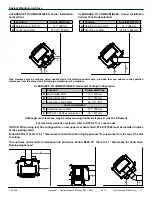
For  corner  installations,  the  clearance  distances  are  14" 

(356mm) from each corner of the stove measured straight 

back  to  the  nearest  combustible  material,  and  21-3/4" 

(552mm) from the chimney connector to the walls. To stay 

within these clearances and have the floor protector touch 

the interior wall it must be a hearth pad size of 53" x 53" 

(USA ONLY).

Alternate floor protector dimension may be used as long as 

they satisfy the measurement requirements shown above.

Type II floor protection must be used.
*Floor protection for the front and sides as measured from 

the appliance door opening.

60”

60”

Interior Wall

Interior W

all

Minimum size floor protection for a corner installation hearth 

pad is 43-3/8" x 32-5/16" (USA ONLY). NOTE: Floor protector 

WILL NOT touch the wall.

J

J

K

L

Floor Protection 

Requirements

US

Canada

J

Sides

8"

203mm

K

Front

18"

457mm

L

Rear

8"

Wall

Summary of Contents for Oakleaf

Page 1: ...to installation Installation MUST comply with local regional state and national codes and regulations Contact local building or fire officials about restrictions and installation inspection requireme...

Page 2: ...origine am ricaine et pi ces import es E F F E REFER TO MANUFACTURER S INSTRUCTIONS FOR CLEARANCES WITH ADDITIONAL VENT CONFIGURATIONS US ENVIRONMENTAL PROTECTION AGENCY Certified to comply with 2015...

Page 3: ...Component Locator 7 D Flue Direction Conversion 7 E Pre Use Checklist 8 4 Dimensions Clearances A Appliance Dimensions 9 B Clearances to Combustibles 10 C Floor Protection 12 5 Chimneys and Venting A...

Page 4: ...n standards Not approved for sale after May 15 2020 MODEL Oakleaf Woodburning Stove LABORATORY OMNI Test Laboratories Inc REPORT NO 135 S2 26 6 2 TYPE Solid Fuel Room Heater Wood Burning Type STANDARD...

Page 5: ...se ventilation by opening windows or doors 2 Make sure the stove doors and lid are closed and latched 3 Check stove for smoking or puffing condition Open by pass and increase air flow to firebox if ne...

Page 6: ...eded to replace what the chimney draws away through the appliance B Fire Safety Maintain the designated clearances to combustibles Insulation must not touch the chimney You must maintain the designate...

Page 7: ...ing upward through the firebox and the open bypass damper loosen the retainer bolts on each of the flue collar and the cast iron plate With the bolts loosened turn the retainer to allow the piece to c...

Page 8: ...clean if applicable 12 The optional air distribution blower has been installed properly 13 A properly grounded electrical receptacle is available within reach of the blower s power cord if installed...

Page 9: ...27 1 4 692mm 29 1 4 743mm 18 15 16 480mm 25 5 8 650mm Centered 27 5 8 701mm When configured for rear flue Floor to center of flue measures 23 1 2 597mm NOTICE When using rear flue configuration a new...

Page 10: ...to single wall connector pipe This lower clearance is based on actual safety test conditions E D B C A E F C A C A D B Vertical Venting Configuration Location Single Wall Pipe A Unit to Side Wall 17...

Page 11: ...Shield Corner to Wall 14 356mm B Vent Pipe to Wall 21 3 4 552mm Location Single Wall Pipe A Shield Corner to Wall 14 356mm B Vent Pipe to Wall 21 3 4 552mm Location Single Wall Pipe A Unit to Side Wa...

Page 12: ...floor protection USA is 32 5 16 Wide By 43 3 8 Deep Parallel versus Corner Installations A parallel installation is one in which the back and sides of the stove are parallel to the walls behind and to...

Page 13: ...through an attic or roof space closet or other concealed space or through a floor or ceiling Whenever possible avoid passing the connector through a combustible wall if you must use an approved wall...

Page 14: ...he highest point at which they exit from the roof Then the chimney must extend 2 ft 0 6m above the highest point within a 10 ft 3m radius Thus the 3 foot 2 foot 10 foot rule 3ft Above roof exit point...

Page 15: ...our plans See Clearances and Floor Protection in this section Since many fireplaces have exposed wooden mantels and trim pay special attention to the clearances necessary to these materials If your fi...

Page 16: ...ace a Floor or Ceiling Chimney Connector Minimum air space with chimney listing Chimney support Attic radiation shield Chimney sections Chimney cap Storm collar Roof flashing Roof radiation shield SS...

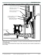
Page 17: ...thimble Flue liner with required air space Minimum of three sheet metal screws per joint of chimney connector Mantel and trim protection Airtight insulated clean out Damper closed and sealed with non...

Page 18: ...ld The Chimney Connector Shall Not Pass Through an Attic or Roof Space Closet or Similar Concealed Space a Floor or Ceiling Combustible Floor Airtight insulated clean out Flue liner with required air...

Page 19: ...ll Not Pass Through an Attic or Roof Space Closet or Similar Concealed Space a Floor or Ceiling Combustible Floor UL1777 Stainless steel liner system or other approved lining system Floor Protection F...

Page 20: ...pace a Floor or Ceiling Minimum clearance from chimney connector to uprotected ceiling 15 Flue liner with required air space Listed or approved thimble assembly 1 Clearance for exterior chimney or 2 c...

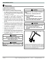
Page 21: ...or protection requirements must be followed 6 Follow the vent manufacturer s instructions when installing in a mobile home 7 Installation shall be in accordance with the Manufactured Home and Safety S...

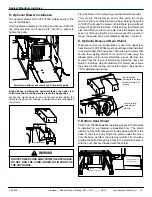
Page 22: ...wall portion 6 Slide the other end of the metal intake flex pipe into the stub on the rear of the Oakleaf and secure it with aluminum tape This air intake will supply outside air for the secondary co...

Page 23: ...er on at any time using the rocker switch on the rear of the blower housing Setting the switch to AUTO will keep the blower off until there is a significant amount of heat from the stove In this setti...

Page 24: ...perating guidelines you will ensure proper draft and gain maximum efficiency and enjoyment from your stove Do not alter the position of the andirons Building a fire too close to the glass may cause da...

Page 25: ...he ash to fall into the ash pan by passing a poker back and forth across the grate The andirons keep the fuel from coming into direct contact with the glass and keep hot coals and embers from spilling...

Page 26: ...epaper and close the loading door s Allow this start up fire to burn for a few minutes keeping the bypass damper open Add about five more pieces of wood in the 2 to 3 inch 50 80mm size range making su...

Page 27: ...The ashes should be the coolest at this time Remove ashes from the fire chamber periodically by raking a poker across the bottom grates Excessive ash buildup can prevent proper venting of exhaust gas...

Page 28: ...chnician A Creosote Formation and Need For Removal When wood is burned slowly it produces tar and other organic vapors which combine with expelled moisture to form creosote The creosote vapors condens...

Page 29: ...eplace gasket as needed Do not operate the stove with a broken glass Replacement glass which is ceramic glass should be obtained only through your Harman dealer To replace a broken glass first be sure...

Page 30: ...dust and pet hair from the blower wheel Reinstall the blower and tighten the two bolts securely 5 Chimney Connector Frequency As necessary Yearly By Qualified Service Technician User At the end of the...

Page 31: ...kleaf Owner s Manual_R23 2010 ___ 09 15 31 3 90 798 Variable Speed Switch Power Cord Blower Thermostat Rocker Grounded to housing Switch Black Wire White Wire 2 1 Oakleaf Optional Blower Kit 1 00 7970...

Page 32: ...acturing Date Active Part number list on following page Cast Iron Wood Stove 1 90 797000 1 Black Sept 2010 thru June 2011 1 90 797000 2 Charcoal 1 90 797000 3 Golden re 1 2 7 6 8 23 22 3 4 5 28 27 26...

Page 33: ...7 Oakleaf Package 3 40 797022 Y Gasket 1 4 Round PSA 15 FT 1 00 2312 Y 8 Ramp Assembly w Gsket 1 10 797109 Y Gasket 1 4 Round PSA 15 FT 1 00 2312 Y 9 Brick Clip Set 1 00 249153 Y 10 Damper Frame Asse...

Page 34: ...50 3 30 1134 50 Y Bolt CB 5 16 18 X 2 Z Pkg of 25 3 30 4001 25 Y Nut FHN 5 16 18 Z 5 Pkg of 100 3 30 8005 100 Y 21 Base Plate Qty 2 req 2 00 797027S 22 Center Brick 3 40 797020 Y Gasket 1 4 Round PSA...

Page 35: ...anty coverage begins on the date of first occupancy of the dwelling or six months after the sale of the product by an independent authorized HHT dealer distributor whichever occurs earlier The warrant...

Page 36: ...y does not cover the following Changes in surface finishes as a result of normal use As a heating appliance some changes in color of interior and exterior surface finishes may occur This is not a flaw...

Page 37: ...Oakleaf Woodburning Stove Dry Seasoned Wood Only Harman Oakleaf Owner s Manual_R23 2010 ___ 09 15 37 3 90 798 Service Maintenance Log Date Of Service Performed By Description Of Service...

Page 38: ...__________________ ________________________________________________________________________________ ________________________________________________________________________________ ___________________...

Reviews: