background image

Harman®  •  P-Series Owner’s Manual_R10  •  2014 - ___  •  11/15

18

3-90-436168c

Whenever adding fuel, take the opportunity to clean the burn 

pot. 

(Weekly at minimum)

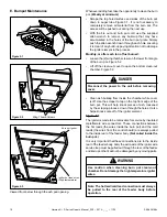
•   Scrape the top holed surface and sides of the burn pot 

down  to  auger  tube  Figure  5.1.  It  is  not  necessary  to 

completely  remove  all  material  from  the  burn  pot. The 

excess will be pushed out during the next use.

•  With  the  fire  out  and  burn  pot  cold,  use  the  supplied 

allen  wrench  to  remove  any  build-up  that  may  have 

accumulated in the holes of the burn pot grate. Simply 

push the allen wrench down through each hole ensuring 

it is clear of any build-up paying attention not to damage 

the igniter element in the process. 

Monthly, or after each ton of fuel burned:

•  Loosen the (2) wing thumb screws on the lower front angle 

of the burn pot. Figure 5.2

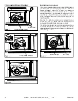
•  Lift off the clean-out cover to open the bottom clean-out 

chamber. Figure 5.3

•  Clean ash buildup from inside the chamber while cover 

is off. Use the scraper to tap on the top front edge of the 

burn pot. This will help knock pieces of ash, loosened 

by the scraping process, down through the holes. It also 

helps knock scale off of the igniter element.

Figure 5.3

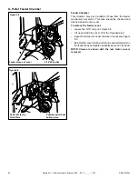
The igniter is made to be removable for service by insulated 

male/female wire connectors. These connections between 

the hot leads (the wires inside the burn pot) and the cold 

leads (the wires from the control board) are always pulled 

to the inside rear of the feeder body.

 (Not coiled inside the 

burn pot.)

It is very important that these connections are to the inside 

rear of the feeder body. Also, the extra wire of the igniter wire 

service loop must be pulled out through the rear of the feeder 

and tied up so that it will not be damaged by any moving parts. 

Note: The hot lead/cold lead connection must always 

be pulled to the rear of the feeder body before 

operation.

Viewed from below through the ash pan opening.

Igniter hot lead wires

(High temperature)

Burn pot igniter

E. Burnpot Maintenance

Figure 5.1

Figure 5.2

Figure 5.3

Wing Thumb Screws

Use caution when cleaning burn pot clean-out 

chamber. Do not damage the high temperature igniter 

wires.

WARNING

!

Disconnect the power to the unit before removing 

cover.

DANGER

!

Summary of Contents for P43

Page 1: ...enandadultstohazardsofhightemperatures High temperatures may ignite clothing or other flammable materials Keep clothing furniture draperies and other flammable materials away HOT SURFACES Glass and ot...

Page 2: ...eater needs periodic inspection and repair for proper operation Consult the owner s manual for further information It is against federal regulations to operate this wood heater in a manner inconsisten...

Page 3: ...gency Manual Ignition 26 E Service Parts 27 P43 27 P61A 31 P68 36 F Contact Information 42 Contains updated information 1 Welcome A Congratulations 2 B Limited Lifetime Warranty 4 2 Product Specific a...

Page 4: ...f new home construction warranty coverage begins on the date of first occupancy of the dwelling or six months after the sale of the product by an independent authorized HHT dealer distributor whicheve...

Page 5: ...S This warranty does not cover the following Changes in surface finishes as a result of normal use As a heating appliance some changes in color of interior and exterior surface finishes may occur This...

Page 6: ...S627 00 ULC ORD C 1482 M1990 UM 84 HUD MODEL P43 Pellet Stove LABORATORY OMNI Test Laboratories Inc REPORT NO 135 S 23 4 135 S 23b 6 2 TYPE Pellet Fueled Supplementary For Residential Use STANDARD s...

Page 7: ...ency using data collected during EPA emissions test Weighted average HHV efficiency using data collected during EPA emissions test A range of BTU outputs based on EPA Default Efficiency and the burn r...

Page 8: ...in front or to the sides of the appliance High temperatures may ignite clothing furniture or draperies Mantel Avoid placing candles and other heat sensitive objects on mantel or hearth Heat may damage...

Page 9: ...r scale marked from 1 to 7 Mode Selector Allows you to choose between Room Temp Mode Constant burn Mode or OFF Also allows you to vary the distribution blower speed by turning the knob to the high or...

Page 10: ...ing heat from your home Damp pellet fuel could turn back into sawdust which does not flow properly through the feed system NOTICE Hearth Home Technologies is not responsible for stove performance or e...

Page 11: ...igh After burning approximately 7 10 minutes the appliance will then burn at the rate at which it was originally set If the appliance is set at one of the lower settings it will run quieter but take l...

Page 12: ...stics test to insure the control is operating properly This is normal 3 For your first fire it may be necessary to purge the auger system by putting the feed limit knob to Test prior to starting the u...

Page 13: ...temp mode however the blower will turn on and off in accordance to what temperature the room sensor is reading When the room sensor is satisfied the blower will shut down until the room sensor sees a...

Page 14: ...r element to operate if the view door is open 4 Adjust Feed Limit If this is your first fire or you are trying different pellets set the feed limit to 4 Figure 4 6 This is a conservative number and wi...

Page 15: ...tant fuel consumption rate is sacrificed for exact room temperature Therefore as it gets colder more pellets will be burned automatically The distribution blower speed will vary according to the posit...

Page 16: ...hese are recommendations Clean more frequently if you encounter heavy build up of ash at the recommended interval or you see soot coming from the vent Not properly cleaning your appliance on a regular...

Page 17: ...e self adhesive 1 4 gasket material around the front face of the glass Set the glass panel and gasket gently onto the door Install the hold down clips and tighten with bolts Glass Cleaning Sometimes i...

Page 18: ...e burn pot This will help knock pieces of ash loosened by the scraping process down through the holes It also helps knock scale off of the igniter element Figure 5 3 The igniter is made to be removabl...

Page 19: ...ke cover pull towards the front of the unit while sliding to the right Figure 5 6 Now that the combustion intake cover is removed you can remove any flyash or debris that has collected around combusti...

Page 20: ...16 wing nut Figure 5 8 Lift up and slide the cover off of the threaded stud Inspect and clean the inner chamber if necessary Figure 5 9 Reinstall the cover making certain it is seated properly on the...

Page 21: ...will not start in AUTO with this status error 5 Blinks In Igniter Auto Mode Only Indicates that the unit has failed to light within the 36 minute start cycle To reset Turn Mode Selector to OFF then tu...

Page 22: ...it burns on low the more frequent cleaning of the glass is required 4 Glass has turned dirty 4 Excessive build up of ash The lower burn settings will produce more ash the higher burn settings produce...

Page 23: ...low blocked flue 3 Something is restricting fuel flow 4 Hopper lid not closed properly 5 Feed motor or combustion blower has failed SMOKE IS VISIBLE COMING OUT OF VENT 1 Air fuel ratio is too rich a...

Page 24: ...iner until all cinders have thoroughly cooled Soot and fly ash Formation and need for removal The products of combustion contain small particles of fly ash The fly ash will collect in the exhaust vent...

Page 25: ...ty control There are 2 high limits one normal operation high limit and one backup high limit The control has an automatic diagnostic circuit that continuously monitors the ESP and Room Sensor for faul...

Page 26: ...l remain shut down If the fire is out and the ESP is still warm the feeder may restart Since the fire is out the ESP temperature will not rise The unit will then shut down and may flash a six blink st...

Page 27: ...RT NUMBER 1 Hopper Assembly 1 10 04300 Y Hopper Knob Post 008168147 1 00 02000 1 Hopper Lid w Hinge Swell Latch Pre 008168147 1 10 08518 Hopper Lid w Hinge Knob Post 008168147 1 10 773900 Hopper Switc...

Page 28: ...ake Assembly 1 10 06810A 2 5 Gasket Feeder Air Intake Pkg of 6 3 44 72224 6 Y 2 6 UL Feeder Air Intake 1 10 72222 2 7 Gasket Ultra Air Intake Pkg of 10 3 44 677160 10 Y 2 8 Ultra Feeder Weldment 1 10...

Page 29: ...0 08516S Y 12 Retainer Assembly 1 10 08533S Y 13 Ash Pan 1 10 7738108A Y 14 Ash Door Assembly Pre 008168147 1 10 7738106A Post 008168147 1 10 773904A Wood Handle Pkg of 3 3 40 08746 3 15 Bolt on Hinge...

Page 30: ...lpipe Pkg of 5 1 00 07381 Y Gasket Hopper Lid 1 00 00248 Y Gasket Hopper Throat 3 44 677185 Y Gasket Over re Air Burnpot 3 44 724114 Y Glass Clip Pkg of 4 1 00 249140 Y Hopper Muf er and Fitting 1 set...

Page 31: ...ed at Depot ITEM Description COMMENTS PART NUMBER 1 Hopper Assembly Pre 008085092 1 10 08622 Y Post 008085092 1 10 05803 Hopper Extension Switch Kit 1 00 06826 Y Hopper Knob Post 008093438 1 00 02000...

Page 32: ...t 1 10 06461 2 3 Feeder Weldment 1 10 677150 Y 2 4 Slide Plate Assembly 1 10 08037 Y 2 5 Pusher Arm Assembly 1 10 06691 Y 2 6 Feed Cover and Gasket 2 Sets 1 00 677152 Y 2 7 Auger Assembly 3 50 00465 Y...

Page 33: ...r Air Intake Pkg of 6 3 44 72224 6 Y 3 6 UL Feeder Air Intake 1 10 72228 3 7 Gasket Ultra Air Intake Pkg of 10 3 44 677160 10 Y 3 8 Ultra Feeder Weldment 1 10 724132 Y 3 9 UL Feeder Pusher Arm 1 10 67...

Page 34: ...2P Y 12 Comb Intake Weldment 1 10 08516S Y 13 Retainer Assembly 1 10 08533S Y 14 Ash Pan 1 10 05800 Y 15 Ash Door Assembly Pre 008093438 1 10 06724S Post 008093438 1 10 06798A Wood Handle Pkg of 3 3 4...

Page 35: ...Load Door 30 Ft 1 00 00888 Y Gasket Burn Pot Tailpipe Pkg of 5 1 00 07381 Y Gasket Hopper Lid 1 00 00248 Y Hopper Lid W Hinge Swell Latch Pre 008093438 1 10 09109 Y Hopper Lid w Hinge Knob Post 00809...

Page 36: ...ed at Depot ITEM Description COMMENTS PART NUMBER 1 Hopper Assembly Pre 008280309 1 10 06709 Y Post 008280309 1 10 00688 Hopper Extention Switch Kit 1 00 06826 Y Hopper Knob Post 008295042 1 00 02000...

Page 37: ...embly Pre 008280309 1 10 07806 2 1 Air Intake Damper Assembly 1 10 06466W 2 2 Air Intake Weldment 1 10 06461 2 3 Feeder Weldment 1 10 677150 Y 2 4 Slide Plate Assembly 1 10 08037 Y 2 5 Pusher Arm Asse...

Page 38: ...embly 1 10 06810A 3 5 Gasket Feeder Air Intake Pkg of 6 3 44 72224 6 Y 3 6 UL Feeder Air Intake 1 10 72228 3 7 Gasket Ultra Air Intake Pkg of 10 3 44 677160 10 Y 3 8 Ultra Feeder Weldment 1 10 724132...

Page 39: ...Cover Right 2 00 06468 2P Y 12 Door Latch Assembly 1 00 06713 Y Contains Latch Adjustment SHCS 1 4 20 X 1 Lock Nut 1 4 X 20 Jam Nut HX Jam 1 4 20Z Steel Bushing 13 Comb Intake Weldment 1 10 08516S Y 1...

Page 40: ...1 00 00959 Y Draft Meter Assembly 1 00 00637 Y Draft Meter Bolt and Tube 1 00 04004 Fuse 6 Amp Pkg of 5 3 20 49447 5 Y Gasket 1 4 Rope Black W PSA Glass 15 Ft 1 00 2312 Y Gasket 3 8 Rope White LD Ash...

Page 41: ...and serial number when requesting service parts from your dealer or distributor Stocked at Depot ITEM Description COMMENTS PART NUMBER Leaf Door Trim Gold 3 43 06717 4 Brushed Stainless 3 43 06717 7 B...

Page 42: ...___________________________________________________________________________ ________________________________________________________________________________ ___________________________________________...

Reviews: