background image

2

Super-Magnum Coal Stoker Stove

Do Not Burn Wet Coal!

3-90-02702R6_03/13                                                      

Hearth & Home Technologies welcomes you to our tradition of excellence! By choosing a Harman appliance, you have become 

part of a long standing family committed to meeting the heating needs of consumers with the most distinctive, powerful and 

responsible home heating products available. 

The  Super-Magnum  has  huge  features  in  an  elegant  package,  giving  you  5000  to  100,000+  BTU  when  you  need  it, 

automatically. You need only set your desired room temperature, keep the hopper full, and the ash pan empty. With the 

Super- Magnum, you will notice even heat throughout your zone and a level of convenience you never thought possible. The 

Super-Magnum takes advantage of Harman’s 30+ years of stove design, technology and manufacturing. This high output 

stove has Super-Smart controls coupled with minimal maintenance. Output is managed by a microprocessor that senses the 

room temperature and the fire temperature with two thermistor probes and then determines the best feed rate for your heating 

demand. The platinum combination is Harman’s Patented Verti-Flow

TM

 Feeder system, and ESP Control which have been 

developed to their highest state. These features work together to allow amazing heat output with little regard for fuel quality.
We wish you and your family many years of enjoyment in the warmth and comfort of your hearth appliance.
Thank you for choosing Harman Home Heating.

Harman Home Heating

A division of


Hearth & Home Technologies

352 Mountain House Road

Halifax, PA 17032

www.harmanstoves.com

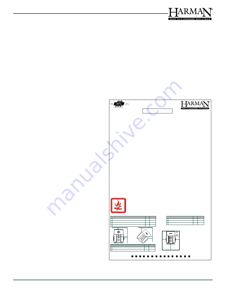
When This Room Heater Is Not Properly 

Installed, a House Fire May Result. To Reduce 

The Risk Of Fire, Follow The Installation 

Instructions. Contact Local Building Or Fire 

Officials About Restrictions And Installation 

Inspection Requirements In Your Area.

Floor protection must be a non-combustible material, and 

must also be placed under any horizontal sections of chimney 

connector pipe, extending 2” (51mm) 

beyond the measurement of the pipe.

Pour protéger le plancher, il faut sous 

le poêle un matériau non combustible, 

qui doit aussi être placé sous les 

parties horizontales du tuyau de 

raccord à la cheminée et s’étendre à 

51 mm (2 po) au-delà de la mesure du 

tuyau.

A C

D

B

F

E

E

C
D

B

A

Parallel 

Installation

Inches

Millimeters

Back Wall To Hopper / Entre mur arriereet l’appareil
Side Wall To Unit / Entre mur lateral et l’appareil
Back Wall To Flue Pipe / Entre  tuyau et le mur arriere
Side Wall To Flue Pipe / Entre tuyau et le mur lateral

2              51

17            432

24            610

34            864

F

E

Corner 

Installation

Inches

Millimeters

Walls to Unit Body / Entre mur adjacent et l’appareil
Walls to Flue Pipe / Entre tuyau et le mur adjacent

15           381
24           610

J

H

G

Floor Protection 

Requirements

Inches

Millimeters

Sides / Côtés
Front- from glass/Devant, par rapport au verre
Rear / Arrière

8             203

 12           305

18            457

Report #/ Raport # 135-S-24-6.2

Tested to / Testé à: UL1482, 

UL 391, and ULC S627-00 

Test Date: July 2009

Approved For Use in Mobile/Manufactured Homes- 

USA ONLY

This appliance is also approved for installation into a shop.

“PREVENT HOUSE FIRES”

Install and use only in accordance with manufacturer’s installation 

and operation instructions and local codes. In absence of local 

codes, installation must meet minimum requirements of NFPA 211 

in USA. Refer to manufacturer’s instructions and local codes for 

precautions required for passing chimney through a combustible 

wall or ceiling. 

WARNING FOR MANUFACTURED HOMES: (US Only) Do not 

install appliance in a sleeping room. An outside air inlet must be 

provided. The structural integrity of the manufactured home’s fl oor, 

walls, and ceiling must be maintained.

Refer to manufacturer’s instructions and to local codes for 

precautions required for passing chimney through a combustible 

wall or ceiling. 

Flue connector pipe must be 6” diameter, minimum 24 MSG blue 

steel. Chimney must be factory built 103HT or masonry construction.

DO NOT CONNECT THIS APPLIANCE TO A CHIMNEY FLUE 

SERVING ANOTHER APPLIANCE.

FOR USE WITH ANTHRACITE “RICE” COAL ONLY

 Do not burn 

wet coal.

DO NOT Overfi re - If Heater or chimney connector glows, you 

are overfi ring.

Input Rating Maximum: 7.75 lb. Fuel/hr.

Electrical Rating: 115 VAC, 60 Hz,3.1 AMPS

Route power cord away from unit. 

DANGER:

 Risk of electrical shock. Disconnect power supply before 

servicing. For further instruction, refer to owner’s manual.

Replace glass only with 5mm ceramic, available from your dealer.

Appliance must be installed with the legs attached. Do not obstruct 

airfl ow under the appliance.

DANGER: 

Risk of Fire or Explosion - Do not burn garbage, 

gasoline, drain oil or other fl ammable liquids.

WARNING: 

Risk of Fire

Do not operate with fl ue draft exceeding -0.080 in water 

column.

Do not operate with fuel loading or ash removal doors open.

Do not store fuel or combustibles within marked clearances.

Inspect and clean fl ues and chimney regularly.

Super Magnum Coal Stoker Stove

Poêle à charbon Super Magnum

Room Heater- Coal Burning

 Appareil de chauffage d’appoint au charbon

Serial No.

№ de série

CLEARANCE TO COMBUSTIBLES /


DISTANCES MINIMALES DE SECURITE:

Date of Manufacture / Date de fabrication:

2009  2010  2011  JAN   FEB   MAR   APR   MAY   JUN   JUL   AUG   SEP   OCT   NOV   DEC

Fabriqué par: Harman Home Heating 352 Mountain House Road, Halifax PA 17032 (É.-U.)

P.N. 3-90-02700

IGN

CAUTION: HOT WHILE IN OPERATION. DO NOT TOUCH. KEEP CHILDREN AND CLOTHING AWAY. 

CONTACT MAY CAUSE SKIN BURNS. SEE NAMEPLATE AND INSTRUCTIONS. KEEP FURNISHINGS 

AND OTHER COMBUSTIBLE MATERIALS A CONSIDERABLE DISTANCE AWAY FROM THIS APPLIANCE.

ATTENTION: CHAUD LORS DU FONCTIONNEMENT.  NE TOUCHEZ PAS L’APPAREIL.GARDEZ LES 

ENFANTS ET LES VÊTEMENTS ÉLOIGNÉS. TOUT CONTACT PEUT ENTRAÎNER DES BRÛLURES DE 

LA PEAU.  RÉFÉREZ-VOUS À LA PLAQUE SIGNALÉTIQUE ET AU MODE D’EMPLOI. GARDEZ LE 

MOBILIER ET LES AUTRES MATÉRIAUX COMBUSTIBLES BIEN À L’ÉCART DE L’APPAREIL.

008

Rapport no 135-S-24-6.2

Conforme à UL 1482, UL 391 et ULC S627-00

Date d’essai: Juillet 2009

Homologué pour les maisons mobiles et préfabriquées - É.-U. SEULEMENT

Cet appareil est également homologué pour être installé dans un atelier.

«ÉVITEZ LES INCENDIES DE MAISON»

N’installez et n’utilisez cet appareil que selon le mode d’installation et le 

mode d’emploi du fabricant et les codes locaux.  En l’absence de codes 

locaux, l’installation doit au minimum être conforme aux exigences de 

la norme NFPA 211 aux É.-U.  Voir dans les recommandations du 

fabricant et dans les codes locaux les précautions quant au passage 

d’une cheminée à travers un mur ou un plafond combustible.

MISE EN GARDE POUR LES MAISONS PRÉFABRIQUÉES : (É.-U. 

seulement) N’installez pas cet appareil dans une chambre à coucher.  

Une arrivée d’air de combustion extérieur doit être prévue.  L’intégrité 

structurelle du plancher, des murs et du plafond de la maison 

préfabriquée doit être maintenue.

Voir dans les recommandations du fabricant et dans les codes locaux 

les précautions quant au passage d’une cheminée à travers un mur 

ou un plafond combustible.

Le tuyau de raccord à la cheminée doit être d’un diamètre de 15,25 

cm (6 po), au minimum en acier bleu 24 MSG.  La cheminée doit être 

en métal 103HT d’usine ou construite en maçonnerie.

NE RELIEZ PAS CE POÊLE À UNE CHEMINÉE QUI SERT POUR 

UN AUTRE APPAREIL.

IL NE FAUT UTILISER QUE DE L’ANTHRACITE «RICE»,

 pas du 

charbon mouillé.

Ne  chauffez  pas  TROP.    Si  l’appareil  ou  le  raccord  de  cheminée 

rougit, c’est que le feu est trop puissant.

Consommation maximale : 7,75 lb de carburant/heure

Courant alternatif de 115 V, 60 Hz, 3,1 ampères

Éloignez le cordon électrique de l’appareil.

DANGER: 

Risque de décharge électrique.  Débranchez la prise avant 

tout entretien.  Pour plus de détails, consultez le mode d’emploi.

Ne remplacez le verre que par du verre céramique de 5 mm à obtenir 

de votre détaillant.

L’appareil doit être installé avec ses pieds fi xés.  N’obstruez pas le 

passage d’air sous l’appareil.

DANGER: 

Risque d’incendie ou d’explosion.  Ne brûlez pas d’ordures, 

d’essence, d’huile de vidange ni aucun autre liquide infl ammable.

MISE EN GARDE:

 Risque d’incendie.

N’utilisez pas le poêle avec un conduit de cheminée dépassant -0,080 

de colonne d’eau.

N’utilisez pas le poêle lorsque les portes du foyer et du cendrier sont 

ouvertes.

Gardez le carburant et les matériaux combustibles en dehors des 

dégagements prescrits.

Inspectez et nettoyez fréquemment les conduits et la cheminée.

G

G

H

J

Rev B

Summary of Contents for Super-Magnum

Page 1: ...minimum clearances to combustibles as specified Failure to comply may cause a house fire Check building codes prior to installation Installation MUST comply with local regional state and national codes and regulations Consult local building fire officials or authorities having jurisdiction about restrictions installation inspection and permits Hot will cause burns Do not touch glass until it is co...

Page 2: ...ire If Heater or chimney connector glows you are overfiring Input Rating Maximum 7 75 lb Fuel hr Electrical Rating 115 VAC 60 Hz 3 1 AMPS Route power cord away from unit DANGER Risk of electrical shock Disconnect power supply before servicing For further instruction refer to owner s manual Replace glass only with 5mm ceramic available from your dealer Appliance must be installed with the legs atta...

Page 3: ... Wall Pass Throughs 11 D The Chimney 12 E Draft Test Procedure 14 Section 6 Mobile Home US only A Mobile Home Installation 15 Section 7 Appliance Set Up A Outside Air Attachment 16 B Leveling The Appliance 17 C Optional Heat Transfer kit 17 D Air Filter 17 E Optional Decorative Tile Kit 17 F Optional Door Trim Kit 18 G Room Sensor Installation 18 Section 8 Operating Instructions A Fuel Specificati...

Page 4: ...me of the mobile home and must never be installed in a room designated for sleeping The unit must have provisions for an outside air source when installed in a mobile home C Glass Specifications This appliance is equipped with 5mm ceramic glass Replace glass only with 5mm ceramic glass Please contact your dealer for replacement glass if needed D Electrical Rating 115 VAC 60 Hz 3 1 Amps E BTU Effic...

Page 5: ...rn wet coal the feed rate will likely need increased Doing this once or twice a year will not damage your stove as long as it is hot and burning Damage is caused when the hopper is left with wet coal in it while the stove is cold This will cause rust and corrosion and it is totally the operator s fault After the coal dries for three or four days depending on conditions it will flow and feed proper...

Page 6: ...d in an adjacent room or farther away from the stove you will notice higher temperatures near the appliance B Fire Safety Maintain the designated clearances to combustibles Insulation must not touch the chimney You must maintain the designated air space around the chimney This space around a chimney is necessary to allow natural heat removal from the area Insulation in this space will cause a heat...

Page 7: ..._03 13 C Component Locations Load Door Ash Removal Door Distribution Air Filter Distribution Blower Air Grill Heat Transfer Kit Filler Plate Verti FlowTM Feeder Control Panel Heat Exchange Cleaning Rod Exhaust Sensing Probe ESP Coal Storage Hopper Removable Hopper Lid ...

Page 8: ...urers instructions 9 The chimney meets the minimum height requirements 10 All labels and hang tags have been removed from the glass 11 All plated surfaces have been wiped clean if applicable 12 The room sensor and any additional cable has been installed properly 13 A properly grounded electrical receptacle is available within reach of the unit s power cord Inspect appliance and components for dama...

Page 9: ...9 Do Not Burn Wet Coal Super Magnum Coal Stoker Stove 3 90 02702R6_03 13 4 Dimensions Clearances A Appliance Dimensions ...

Page 10: ... must be located under the appliance and extend beyond the appliance according to the measurements below Floor protection must also extend under any horizontal sections of chimney connector and 2 50 8mm beyond each side of the connector DANGER The appliance legs may not be removed for installation Minimum Size floor protection is 49 Deep By 42 Wide J G Floor Protection Requirements Inches Millimet...

Page 11: ...gauge chimney connector pipe The size of the connector should be 6 inch to match the size of the flue collar opening Do not use makeshift components No part of the chimney connector may pass through an attic or roof space closet or other concealed space or through a floor or ceiling Whenever possible avoid passing the connector through a combustible wall if you must use an approved wall pass throu...

Page 12: ... 0 9 m above the highest point at which they exit from the roof Then the chimney must extend 2 ft 6 m above the highest point within a 10 ft 3 m radius Thus the 3 foot 2 foot 10 foot rule 3ft Above roof exit point 2ft Higher than anything within 10ft of the chimney NOTE The restriction of not venting more than one appliance to the same flue applies to the U S specifically While it is not recommend...

Page 13: ...ey When connecting to a masonry chimney several provisions are standard First whether the chimney connector is vented to the chimney through a thimble or a breech pipe neither must pass beyond the inner surface of the chimney liner and both must be firmly cemented in place with refractory cement A thimble is a masonry pipe which is inserted through the chimney wall and is frequently the preferred ...

Page 14: ...ff after the test with a bolt Attach the draft meter to the hole in the connector Agreat chimney will have draft without a fire or heat source Set the barometric damper to maintain 06 to 08 inches of water column Remove the draft meter from the connector pipe and seal the hole by threading in a screw or bolt You may also want to apply a small dab of high temperature silicone to the threads prior t...

Page 15: ...rer s instructions when installing in a mobile home 7 Installation shall be in accordance with the Manufactured Home and Safety Standard HUD CFR 3280 Part 24 8 The appliance must never be installed in a room designated for sleeping This diagram shows the bracket that was used to bolt the stove to the pallet Use at least two of these brackets for securing the appliance through the floor in a mobile...

Page 16: ...reciprocating saw You ll want the hole to be just slightly larger than the metal flex pipe 4 Attach the rodent screen to one end of the flex pipe and insert it through the wall until the back of the screen cover is against the outside surface 5 Hold the flex pipe in place to make an accurate determination of the length needed Cut the flex pipe to length 6 Slide the trim ring onto the flex for the ...

Page 17: ...ow through the duct pipe D Air Filter To ensure cleanliness of the air circulated through the heat exchange the Super Magnum is equipped with a replaceable filter The filter is located under the stove To remove the filter loosen the two thumb screws and remove the cover Slide the filter out the open slots in the front of the channel Check the filter for damage change if necessary Replacement filte...

Page 18: ... 1 To Install the air grill remove the existing painted grill Then using the same two screws and spring washers install the brushed stainless grill G Room Sensor Installation Although not required it is recommended that the room sensor be connected in every installation Using a minimum size 18 gauge wire you may splice in an additional length to extend the room sensor The following are typical loc...

Page 19: ... Room Temp mode where the control will adjust the rate of burn to meet a specified room temperature setting Regardless of the mode selected operation is controlled by both exhaust temperature being reported by the ESP Exhaust Sensing Probe and the microprocessor circuit board We ll discuss these control devices and their functions now 1 ESP Exhaust Sensing Probe The ESP is a tiny thermistor locate...

Page 20: ...s and demand temperature The circuit board also has the ability to self diagnose when things are not happening as they should be Feed adjuster Sets the maximum feed rate Test Runs all motors at full speed for one minute to check operation After two minutes the stove will go to minimum burn and the blowers will alternate from high to low every minute to remind you that you are still in Test Mode Di...

Page 21: ...ill adjust the feed rate to maintain the desired temperature setting in the room For best results be sure the room sensor is located outside of any drafty areas and not positioned on the floor or near an exterior wall Stove Temp mode is more of a manual method of operation The stove will run at a constant heat output regardless of outside air temperature Note that on the coldest days your indoor h...

Page 22: ...ating to increase the fire size NEVER APPLY STARTING GEL TO THE STARTING MIXTURE WITHOUT THE COMBUSTION BLOWER OPERATING NEVER USE GASOLINE GASOLINE TYPE LANTERN FUEL KEROSENE CHARCOAL LIGHTER FLUID OR SIMILAR LIQUIDS TO START OR FRESHEN UP A FIRE IN THIS HEATER KEEP ALL SUCH LIQUIDS WELL AWAY FROM THE HEATER WHILE IN USE E Fire Characteristics After lighting the fire it will go through a few diff...

Page 23: ...is cold Re set restrictor using draft meter Be sure that the blower is in its mount Remove grates and clean air chamber Follow start up procedure Replace ESP Unburned or partially burned coal in ash pan Black rocks in coal Feed rate too high Try different coal Set feed adjuster to lower setting Coal pushing out the sides of the grate frame Clinkers in ashes restricting flow of fuel over the burn g...

Page 24: ...y OR X Firebox thorough cleaning End of heating season OR X Glass When veiw of fire becomes obstructed OR X Heat exchanger Chain scraper Whenever filling the unit hopper OR X Hopper Whenever adding fuel OR X Venting system More frequently depending on fuel quality and quantity OR X Soot Formation and Need For Removal When coal is burned the products of combustion combine with moisture to form a so...

Page 25: ...ed from the stove you can flip the carry handle up for convenience Ashes must be placed in a metal container with a tight fitting lid The closed container of ashes should be placed on a non combustible floor or on the ground well away from all combustible materials pending final disposal If the ashes are disposed of by burial in soil or otherwise locally dispersed they should be retained in the cl...

Page 26: ...glass Apply the cleaner to the cloth then wipe the glass Fly ash allowed to accumulate on the glass may lead to permanent fogging or crazing of the glass Inspect the glass and sealing gasket Replace gasket as needed Do not operate the stove with a broken glass Replacement glass which is ceramic glass should be obtained through your Harman dealer To replace a broken glass first be sure to carefully...

Page 27: ...oreign objects This is also a good time to vacuum any coal residue or dust from the hopper Remember to empty and clean the hopper at the end of the burn season or whenever the stove is not going to be operated for a few days This will help to prevent rust formation in the hopper and feed system 7 Firebox Frequency As necessary Yearly By User Cleaning the firebox and internal heat exchange surfaces...

Page 28: ...ance to be sure there are no bird nests or the like D Motors and Components 1 Feed Motor Requires no lubrication Keep the motor windings free of dust Can be wiped clean or vacuumed To remove feed motor Remove rear access panel and open left rear door Remove feed shaft shield by pushing with thumb where shown and lift up while pulling out Set Screw Mounting Screws 2 Combustion Blower Requires no lu...

Page 29: ...ss the panel in the fuel hopper Remove the knob from the heat exchange scraper handle The knob is threaded onto the shaft Remove the access panel by loosening the screws With a 1 4 socket or driver remove the screw that attaches the probe Pull the probe out of it s mounting hole Scraper Knob Access Cover ESP probe 5 Fines Scraper in feeder In the base of the hopper there is a scraper plate that ke...

Page 30: ... 120 VOLTS A C 60 HZ ROOM SENSOR 6 AMP GLASS FUSE EXHAUST SENSING PROBE BOARD BLACK WHITE BLACK BLACK GREEN LABEL PART NO 3 90 02703 11 PIN CONNECTOR WHITE BLACK GREEN HARMAN SUPER MAGNUM COAL STOKER 1 90 02700 COMBUSTION FAN BROWN BLACK WHITE WHITE WHITE BLACK WHITE RED WHITE BLUE GREEN GREEN DISTRIBUTION FAN 11 PIN CONNECTOR BLACK WHITE 11 Reference Materials ...

Page 31: ...nufacturing Date July 2009 Ending Manufacturing Date Active Part number list on following page 1 90 02700 1 34 33 32 31 30 29 35 37 38 28 26 24 23 39 40 41 43 36 42 20 21 22 19 18 17 1 6 7 8 9 5 2 3 4 27 16 15 14 13 12 11 10 25 03 13 Coal Stove ...

Page 32: ...2001 50 Y 13 Steel Sleeve Bushing 1 2 OD x 3 4 Handle Kit 3 50 05230 14 1 4 20 x 1 1 2 Grade 8 Yellow Zinc Hex Head Cap Screw Pkg of 25 3 30 1119 25 Y 15 Adjuster Plate 2 00 06713D 16 1 4 20 Grade C Zinc Plated Top Lock Nut Pkg of 50 3 30 8021 50 Y 17 3 8 16 x 1 Grade 5 Zinc Plated Hex Cap Screw Pkg of 50 3 30 1134 50 Y 18 5 16 18 Grade 5 Zinc Plated Finished Hex Nut Pkg of 100 3 30 8005 100 Y 19 ...

Page 33: ...0x5 8 Hex Washer Slot T23 Zinc Thread Cutting Screw Pkg of 50 3 30 1111 50 Y 3 8 16 x 1 4 Alloy Steel Black Oxide Cup Point SSS Pkg of 25 3 30 2014 25 Y Air Grill Brushed Stainless 3 43 02726 7 Ash Door Tile Frame Brushed Stainless 3 43 02729 7 Ball Plunger 5 16 x 1 2 Pkg of 3 3 31 5500 3 Ball Spring Bracket 2 00 06714 Brick Full skid 414 Pcs 3 40 900450 414 Door Hinge w Pin Qty 2 req 3 00 773813 ...

Page 34: ...ade 5 Zinc Plated Hex Cap Screw Pkg of 50 3 30 1122 50 Y 43 4 Pusher Arm Weldment 1 10 02708W Y 43 5 5 16 18 Grade 5 Zinc Plated Finished Hex Nut Pkg of 100 3 30 8005 100 Y 43 6 Pillow Block 3 31 324122 Y 43 7 1 4 20 Zinc Plated Finished Hex Nut Pkg of 100 3 30 8004 100 Y 43 8 HCS 1 4 20 X 1 2 Pkg of 50 3 30 1108 50 Y 43 9 SH Shoulder Screw 5 16 18 X 3 8 X 3 8 3 30 131180759 43 10 Pusher Block 3 5...

Page 35: ...ted Hex Cap Screw Pkg of 50 3 30 1122 50 Y 44 5 Laser Cam Assembly 1 10 02764A Y 44 6 Pillow Block 3 31 324122 Y 44 7 5 16 18 Grade 5 Zinc Plated Finished Hex Nut Pkg of 100 3 30 8005 100 Y 44 8 Extension Shaft 2 00 02706 Y 44 9 Back Cover 2 00 02705B 44 10 Wire Cover 2 00 02773B 44 11 Grommet 7 16 ID X 3 4 OD 3 31 960021 44 12 HWH TCS 10 24X3 4 BLACK OX TYPE F Pkg of 50 3 30 1102 50 Y 44 13 Pelle...

Page 36: ...ction warranty coverage begins on the date of first occupancy of the dwelling or six months after the sale of the product by an independent authorized HHT dealer distributor whichever occurs earlier The warranty shall commence no later than 24 months following the date of product shipment from HHT regardless of the installation or occupancy date The warranty period for parts and labor for covered ...

Page 37: ...ty does not cover the following Changes in surface finishes as a result of normal use As a heating appliance some changes in color of interior and exterior surface finishes may occur This is not a flaw and is not covered under warranty Damage to printed plated or enameled surfaces caused by fingerprints accidents misuse scratches melted items or other external sources and residues left on the plat...

Page 38: ...38 Super Magnum Coal Stoker Stove Do Not Burn Wet Coal 3 90 02702R6_03 13 Service Maintenance Log Date Of Service Performed By Description Of Service ...

Page 39: ...39 Do Not Burn Wet Coal Super Magnum Coal Stoker Stove 3 90 02702R6_03 13 Service Maintenance Log Date Of Service Performed By Description Of Service ...

Page 40: ...100 Recycled Paper At Harman we build each product to a standard not a price Signature of Boxer Your premium quality hearth product designed and assembled by the experienced and skilled members at Harman in Halifax PA USA ...

Reviews: