background image

Make Wiring Connections at Header

115 VAC 15 amp

Power Connection

1.

Connect to power.

2.

Plug-in Call-Send cables.

3.

Plug-in Interlock cables

Header

Route wires
though the
knockouts in
the header

Call-Send Cables

-Connectors are the same.

-Cables are supplied in different

lengths.  The shortest cable

goes to the upper floor, etc.

Interlock Cables

-see notes below

Plug into mating
connectors

Wires from Travel Cable

Upper Interlock

Middle Interlock

(

3-Stops only

)

Lower Interlock

Interlock Cable Note:

The connectors for the interlocks are
different to prevent being plugged into
the wrong interlock.

The photo to the right shows the orienta-
tion of the connectors at the header.

630-00092- Rev. 

B

Summary of Contents for Ascent DW100

Page 1: ...iring connections at Header 7 Run lift in up direction using temporary pendant control to wind the steel cable onto the drum 8 Mount Cams on Track 9 Install Interlocks 10 Test in Automatic Operation 11 Attach Header Cover and Shroud Note Harmar designs the dumbwaiter to meet the requirements of ASME A17 1 Installer to check with local authorities to assure local and state code compliance installat...

Page 2: ...630 00092 Rev B ...

Page 3: ...Remove Shroud The Shroud is held on with 4 socket head screws 1 8 allen wrench Shroud Car sheet metal panels Trolley Gear Box Door Frame Door Switch Door Panel Motor 630 00092 Rev B ...

Page 4: ...630 00092 Rev B ...

Page 5: ...eces of foam do not remove the pieces of foam until installation is complete Attach to wall with 14 x 2 wood screws Bracket Locations 6 from each end of track 12 from each side of track splice Note In some applications it may be necessary to remove the car from the trolley Stand the assembly up and into place inside the hoistway consult the application drawing for proper placement Square Nut 630 0...

Page 6: ...630 00092 Rev B ...

Page 7: ...the car in place during shipment Remove and discard the bracket Important Uncoil the Steel Drive Cable and Travel Cable ensuring they are not twisted Remove Shipping Wire Ties holding the Steel Drive Cable and Travel Cable together Steel Drive Cable Travel Cable 630 00092 Rev B ...

Page 8: ...630 00092 Rev B ...

Page 9: ...allen wrench and slide the bars half way out and re tighten the set screws Slide the Track and Splice Bars into the Track mounted to the wall Tighten all set screws when the track joint is properly aligned Attach the track to the wall with track brackets continued on next page Match track pieces to the corresponding letter A to A B to B 630 00092 Rev B ...

Page 10: ...al adjustment can be made after the middle landing cam is adjusted The sliding cam rides along with the car when the car is at or above the middle landing stop The switch tells the controller which direction to run when a middle call is registered Sliding Cam Insert Sliding Cam into slot of Track Sliding Cam Stop Loosen screw to adjust to proper height 630 00092 Rev B ...

Page 11: ... Tapped screw holes are for attaching the Header Cover later in the Installation Insert end of Steel Cable into Header The Travel Cable runs down this side of the Track Secure Travel Cable inside the Track above black plastic chain with adhesive clips adhesive goes against side wall of track Space clips approximately 24 between the plastic chain and track header 630 00092 Rev B ...

Page 12: ...630 00092 Rev B ...

Page 13: ... are supplied in different lengths The shortest cable goes to the upper floor etc Interlock Cables see notes below Plug into mating connectors Wires from Travel Cable Upper Interlock Middle Interlock 3 Stops only Lower Interlock Interlock Cable Note The connectors for the interlocks are different to prevent being plugged into the wrong interlock The photo to the right shows the orienta tion of the...

Page 14: ...630 00092 Rev B ...

Page 15: ... grooves of the drum Ensure that no grooves are skipped or that the cable does not wind over itself Warning All Safety Devices except for the final limit are bypassed when using the pen dant control Temporary Pendant Control Wind the Steel Cable onto the Cable Drum Cable Drum rotates this direction in when running UP 630 00092 Rev B ...

Page 16: ...630 00092 Rev B ...

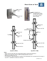
Page 17: ...on of the dumbwaiter if the car should overrun the upper or lower limit It disables all controls when actuated Upper Limit Cam Lower Limit Cam Middle Limit Cam Sliding Cam installed in step 4 48 3 4 Track Track Layout for 2 Stop Layout for 3 Stop Upper Limit Cam Cam attaches to a threaded nut bar inside the slot of the Track nut bar is held in place by pieces of foam Lower Limit Cam Final Limit Ca...

Page 18: ...630 00092 Rev B ...

Page 19: ...ach template to door jamb and mark mounting holes see template for instructions 2 Remove cover from interlock and fasten Interlock to door jamb with 8 wood screws 3 Route 4 conductor Interlock cable through hole in top of interlock and make wire connections A wire 3 B wire Yellow Green C wire 2 D wire 1 ____________________ Interlock Interlock Wiring RDI or CDI continued on next page 630 00092 Rev...

Page 20: ...s with a disabled safety device by anyone other than a person that is servicing it whom has the knowledge of the functionality of this safety Possible risk of injury or death could occur if the safety circuit is bypassed or not functioning properly While the limit switch is actuated there should be 24 VAC between terminals 5 and 6 at the corresponding interlock WARNING If at any time the interlock...

Page 21: ...perable if the car door is open Verify all controls are inoperable if a hoistway door is open Test each hoistway door individually Verify each hoistway door locks when the dumbwaiter car is not parked at that landing Verify all controls are inoperable if the final limit switch is actuated Verify all controls are inoperable if the slack cable device switch is opened Travel Cable Verify that the tra...

Page 22: ...630 00092 Rev B ...

Page 23: ...Complete the Installation 1 Install cover on header 2 Replace shroud 3 Use a permanent marker to mark the installation date on the data plate 630 00092 Rev B ...

Page 24: ...630 00092 Rev B ...

Page 25: ...RE FROM DRAWING DWG NO 25472 DESCRIPTION ASSY Sub 3 Stop Switch Plate DRAWN BY DATE AP 7 24 2007 SIZE B SHEET 1 OF 1 C REV CONFIDENTIAL INFORMATION NOT TO BE COPIED OR USED WITHOUT WRITTEN CONSENT INTERPRET DRAWING AND TOL PER ASME Y14 5 2009 UNLESS OTHERWISE SPECIFIED DIMENSIONS ARE IN INCHES TOLERANCES ARE SCALE 3 4 DECIMALS ANGLES 1 X XX XXX 0 1 0 02 0 010 REVISION HISTORY REV DESCRIPTION BY CH...

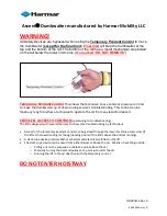
Page 26: ...erify if local code requires Hoistway to be considered a confined space Use the Temporary Pendant Control to move the dumbwaiter inside the hoistway WARNING The safety circuit should only be bypassed during installation or troubleshooting by a qualified technician who understands the functionality of the safety device The dumbwaiter should never be allowed into operation with a disabled safety dev...

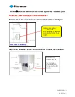
Page 27: ...s a machine access door located below the lower landing door Bottom view of dumbwaiter cab thru machine access door below the lower landing door Machine Access Door 18 x 24 To be normally locked and controlled by Safety Door Switch Bottom side of dumbwaiter cab See instruction manual for using Temporary Pendant Control 630 00092 Rev B ...

Page 28: ...hnician to operate the car from any location desired SERVICE ACCESS TO CONTROLS pertaining to troubleshooting The lift is designed with several features to allow safe troubleshooting by technicians Access for the temporary pendant control can be gained through the lower machine access door if the lift at the lower landing or though landing doors if the lift is above the bottom landing A slack rope...

Reviews: