background image

1500 Independence Blvd, Suite 220 

Sarasota, FL 34234

800.833.0478

harmar.com

Summary of Contents for csl500

Page 1: ...24SEP2021 630 00063 01 REV D HELIX CURVED STAIR LIFT INSTALLATION SERVICE MANUAL ...

Page 2: ......

Page 3: ...hnical Specifications 5 Code Statement 5 PREPARATION 6 Required Tools 6 Included Parts 6 INSTALLATION 7 Battery Installation 9 Chassis Installation 10 Seat Installation 11 Mid Charging Station Installation 12 Supports 13 Charging Station 13 Alignment 14 Final Limit 14 Overspeed 14 Wireless Remote Reprogramming 16 Operational Check 17 TROUBLESHOOTING 18 Controls 18 MAINTENANCE 19 6 Month Maintenanc...

Page 4: ...ad and abide by the message that follows the safety alert symbol NOTE Indicates a condition that should be followed in order for the lift to function in the manner intended SPECIAL CAUTIONS Pay attention to the following Special Cautions while operating your stair lift Do not exceed the maximum payload capacity of 350 lb Make sure any obstructions are cleared from underneath the lift before use Do...

Page 5: ...ler s responsibility to contact their state city or local code enforcement office and determine all the regulations the lift and installation are subject to This must be done before installing lift COMMERCIAL 4 INCLINED STAIRWAY CHAIRLIFTS Section 4 applies to inclined stairway chairlifts installed in locations other than in or at a private residence for use by the mobility impaired 4 1 Runways 4 ...

Page 6: ...ire attached to Fish Tape Emery Sandpaper Fish Tape Lightweight Grease White Lithium Grease Mirror for checking charger Shims Tape Measure Towels for cleaning Wire Stripper Crimper OPTIONAL TOOLS Mounting Screws could be needed based on flooring Pull Strap Ratcheting Strap Volt OHM Meter INCLUDED PARTS Before beginning installation inspect and check that the box contents are complete and undamaged...

Page 7: ... indicate the position of the supports See Figures 3 1 and 3 2 Figure 3 1 NOTE S is the leg position F is the rail stabilizer and does not go to the floor Figure 3 2 NOTE You may complete the wiring while putting the rail together or use a fish tape on the completed unit to run the wire 2 Carry the chair and chassis to the location of the installation Usually this will be at the top of the stairs ...

Page 8: ...ng included with the rail system Run the charging station wire through the lower rail There is a hole at the charger location for it to come out See Figure 3 6 Figure 3 6 5 Check both ends of the rail and wipe clean You may need to clean the ends with Emery paper and add a small amount of grease to help slide the pipes together See Figure 3 7 Figure 3 7 6 Slide the pipes together one at a time sta...

Page 9: ... the rail to the correct angles and check the drawing to verify that all clearances are correct DO NOT tighten all the leg set screws yet only set enough to support the rail Leave the others floating BATTERY INSTALLATION 1 Install the battery Open the front of the chassis by removing the screws on shroud See Figure 3 12 Figure 3 12 2 Install the batteries and connect wires Ensure sure that the bla...

Page 10: ...ing the install switch release the safety or put the wires back together See Figure 3 15 Figure 3 15 CHASSIS INSTALLATION 1 Ensure that the charging strips are oriented on the top of the bottom rail See Figure 3 16 Figure 3 16 2 Install the loading bar See Figure 3 17 Figure 3 17 3 Slide the chassis on until the pinion gear hits the gear rack Activate the installation rocker switch to drive onto t...

Page 11: ...e 3 20 3 Observe the magnet switch for seat safety See Figure 3 21 Figure 3 21 NOTE Lubricate the seat post before installing using a white lithium grease 4 Install the set screw that holds the seat from coming up in collar where the wires for the hand control comes through See Figure 3 22 Figure 3 22 5 Connect the seat rocker switch wires See Figure 3 23 Figure 3 23 6 Reconnect the batteries and ...

Page 12: ...sing the self taping screws provided See Figure 3 25 Figure 3 25 3 Align the charge feet to the chassis and ensure the charge feet are compressing about 1 4 See Figures 3 26 through 3 28 Figure 3 26 Figure 3 27 Figure 3 28 4 Drill the size 3 8 hole in the rack to pull the wire out See Figure 3 29 Figure 3 29 5 Connect the wire to the charge station and ensure the red wire matches the location of t...

Page 13: ...e 3 31 Figure 3 31 NOTE When on carpet tighten down the floating legs first then tighten the set screw on them Loosen the set screws on the legs you were using for support and tighten them to the floor Tighten the sets screws OUTDOOR UNITS 1 After all the legs are set add caulking to all the leg joints including the collars Spray the back of the chassis with some type of corrosion blocker and ensu...

Page 14: ...4 2 Route the red and black wires through the hole provided in the rail by the charging station Use provided grommet to protect the wire 3 Determine which end has the AC power for the power supply Connect the power supply with the provided connector which has a red and black wire to the red and black wires Using the provided terminals attach the charge wire to the wires in the rail See Figure 3 35...

Page 15: ... Figure 3 42 2 If the unit fires due to a runaway situation contact Harmar tech services to evaluate The unit should not be put back in service until the reason for overspeed activation has been determined WARNING To activate the overspeed if you move the arm it will release a jammer that will go between the gear rack and the sprocket and the limit switch will remove power See Figure 3 43 Arm to r...

Page 16: ... will beep once If the remotes need to be re programmed or you have a replacement remote do the following 1 On the wireless control board press and hold the small black button that says pair At the same time hold the up button on remotes for three 3 seconds This will link the board and the remotes to your lift See Figures 3 46 and 3 47 Figure 3 46 Power light Receiving signal light Reset button Pa...

Page 17: ... after testing is complete Test wireless remote in both direction of travel Ensure that all legs are caulked outdoor unit only Corrosion blocking has been applied to chassis outdoor unit only Verify that the Overspeed Shipping Bolt was removed the overspeed feature will not operate with the bolt in place Seat position level at top and bottom If it is not level or customer would like the chair to h...

Page 18: ...t indicates a possible problem Note The unit will beep once when turned on and the wireless remote board will beep once Beeps should be counted after the unit is turned on and the first audible beep 1 2 3 4 5 7 6 Number of Beeps Runaway 1 No 12 volt power on the board 2 Conflicting switches FOOTREST UP and FOOTREST DOWN 3 Conflicting switches OBSTRUCTION UP and OBSTRUCTION DOWN 4 Conflicting switc...

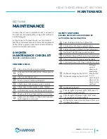
Page 19: ...olling Lubricate seat swivel seat hinge and footrest Check sealant on all legs outdoor units only Apply corrosion block on chassis and exposed metal outdoor units only SAFETY SWITCHES ENSURE SWITCHES ARE WORKING BY ACTIVATING EACH CONDITION Seat locking and seat cut off switch Footrest Up lift stops in up direction Footrest Down lift stops in down direction Rail Guard Up lift stops in up direction...

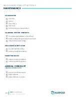
Page 20: ... CONTACTS Top voltage reading between 27 and 29 volt Bottom voltage reading between 27 and 29 volt Charger functionality voltage GEAR RACK SAFETY STOP Top check tightness of stop Bottom check tightness of stop MOUNTING BOLTS Check all rail bolts for tightness Check all leg bolts for tightness ANNUAL CHECKLIST INDOOR OUTDOOR UNITS Same as 6 month maintenance Replace batteries Replace batteries on r...

Page 21: ...HELIX Install Manual 24SEP2021 630 00063 01 REV D 21 NOTES ...

Page 22: ...HELIX Install Manual 24SEP2021 630 00063 01 REV D 22 NOTES ...

Page 23: ...HELIX Install Manual 24SEP2021 630 00063 01 REV D 23 NOTES ...

Page 24: ...1500 Independence Blvd Suite 220 Sarasota FL 34234 800 833 0478 harmar com ...

Reviews: