Chapter 4 Installing HA-675 driver
HA-675_V3_02
- 58 -
◆
Power ON sequence for absolute system ABS
Note 1: The figure above shows the power-ON sequence for the setting [0: ABS-REQ signal] for the
parameter of [parameter mode]
→
[ H: ABS data request timing]. For the setting [1: at control
power-ON], the signal in the block is not necessary.
Note 2: An absolute pulse train for absolute encoder is outputted after around 1 ms of outputting
phase-Z signal.
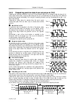
Refer to [3-6-2 Outputting position data from output port: CN2] for outputting position data.
Note 3: The servo-ON signal is unaccepted until completing the transmission of a set of pulse trains by
the [position data request] signal.
Note 4: The [alarm 57] may occur if the encoder rotates more than 127 resolvable position while the
revolution counter is transmitting a pulse train.
Note 5: After turning on the control circuit power, enter Servo ON after turning on the main power even
though the time to turn on the main power is not specified.
4-9-4
Power OFF sequence
Plan the power OFF sequence with the timing shown in the figures below.
Main power
ON
⇒
OFF
Control power
ON
⇒
OFF
CN2-36 Alarm: ALARM
outputting
CN2-3 Servo ON: S-ON
inputting
CN2-6 Start: START
inputting
CN2-28 position data request
ABS-REQ inputting
Note 1
Note1: For the setting [1: at control
power-ON] for [H: ABS data
request timing], the
signal in the
block is not necessary.
Main power
OFF
⇒
ON
Control power
OFF
⇒
ON
CN2-33 Ready: READY
outputting
CN2-48, 49 Phase-Z: Z
outputting
CN2-3 Servo ON: S-ON
inputting
CN2-44, -45, -46, -47 Phase-A, -B:
A+A-B+B-
outputting
CN2-36: Alarm: ALARM
outputting
0ms(min)
90ms(max)
Servo ON
available
.
Note 3
84
μ
s
0ms(min)
4s(max)
3ms(max)
10ms(max)
840
μ
s
90ms(max)
Note 4
Multi-turn
data
Single turn data
Note 2
Incremental
data
*Note 5
Min.0ms
Max.20ms
Min.20ms
Min.0ms
ON
ON
OFF
OFF
Not acceptable
ON
Input
OFF
Alarm
Reset


