47
1019658 11/2014
Size
14
17
20
25
32
40
45
50
58
ca.
∅
Wave Generator
- Main axis
36
43
50
63
82
100
114
125
146
[mm]
Table 47.1
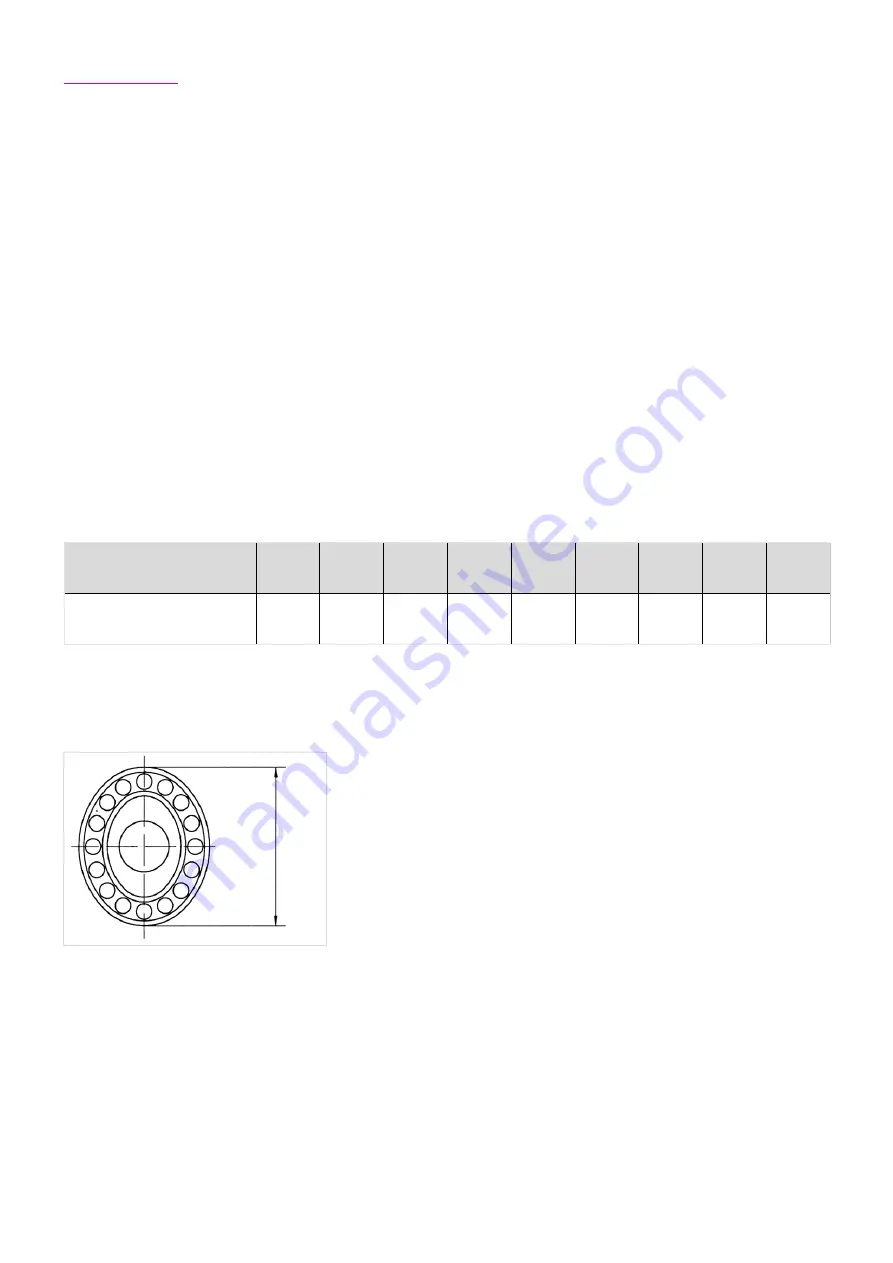
Illustration 47.2
∅
W
av
e G
en
er
at
or
- M
ai
n a
xi
s
5.9 Assembly
The assembly must take place basically without impact. The assembly instructions of the machine manufacturer are to be
considered. All screws must be tightened crosswise in 3 steps to the prescribed torque.
Assembly procedure
The assembling method of the gear depends strongly on the design details. Thus, this assembly manual only comprises
standard information.
Basically first the Circular Spline (CS) and Flexspline (FS) should to be mounted and screwed down. The assembly of these two
components can take place in any order.
The Wave Generator (WG) should be shifted at last into the pre-mounted components Flexspline/Circular Spline. If the
assembling sequence described above cannot be observed please ask Harmonic Drive® whether in the concrete case another
sequence is admissible.
Note:
Before the Wave Generator is set in position, the Circular Spline fixing screws must be tightened. Otherwise the Circular
Spline would deform under the pre-load initiated by the Wave Generator. This could cause the gear to run roughly.
For the planning of the assembly sequence it may be helpful to know the max. diameter of the Wave Generator.
See illustration 47.2. In table 47.1 the diameters of the Wave Generator main axes are indicated.


