Chapter 1 Main Features and Specifications
Back Panel
© 2011 Harmonic Inc.
15
bNSG 9000 & NSG 9000-3G, Rev D
1.6.1.2
DTI Ports
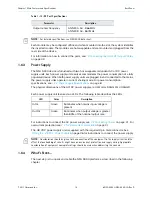
The DTI ports, labeled DTI1 and DTI2, are optional and are operating once a DTI card is
installed. The latter is installed when the NSG 9000 device is operating in an M-CMTS
application. You may purchase a device with the DTI card installed or install it by yourself. For
installation and cabling instructions, see
2.3.2 Installing a DTI Card (Optional)
on page 24.
The following table
lists the DTI ports specifications:
1.6.1.3
ASI Monitoring Port
The NSG 9000 platform may duplicate one of the output transport streams to the ASI output
port designed for monitoring purposes. Use this port to connect to devices that accept ASI
input such as an MPEG analyzer. For cabling instructions, see
3.4 Connecting the ASI
Monitoring Port Cables
on page 30.
1.6.1.4
Module Map
The Module Map is a graphic view of the back panel of the device for ease of use.
1.6.1.5
GbE Input Ports
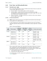
The NSG 9000 platform includes six GbE ports labeled GbE 1- 3 and
GbE 1 - 3. Three ports support Small Form Factor Pluggable (SFP) transreceivers for either
fiber or copper cables and the other three support copper cables for 1000 Base-T cables
only.
Any combination of active ports is supported except for the following:
Copper #1 & SFP #1
Copper #2 & SFP #2
Copper #3 & SFP #3
The following table lists the GbE port specification:
Table 1-8: DTI Ports Specifications
Parameter
Specification
Input signal
Complies with DOCSIS 3.0 DTI
Table 1-9: GbE Port Specifications
Parameter
Specification
Connector
Three receptacles for SFP connectors
RJ-45 connector
Maximum input bitrate
n
Line rate up to 1000 Mbps
n
Processing up to
Maintenance
Swappable


