Chapter 3 Cabling
Cabling the GbE Ports
© 2011 Harmonic Inc.
29
bNSG 9000 & NSG 9000-3G, Rev D
3.2
Cabling the GbE Ports
To connect the GbE port to the GbE switch, use either of the following:
Multimode or single-mode optic fiber with an LC connector. The LC connector plugs into
an SFP receptacle and accommodates two fibers, one for transmission and the other for
reception.
Shielded and grounded CAT-6 or CAT-7 cable with an RJ-45 connector. The RJ-45
connector plugs into a copper SFP receptacle or a built-in RJ-45 connector.
The GbE ports are either fiber/copper or copper only ports. The following configuration of
GbE ports is not supported:
GbE 1 fiber/copper and GbE1 copper,
GbE 2 fiber/copper and GbE 2 copper
GbE 3 fiber/copper and GbE 3 copper
NOTE:
GbE port redundancy is not supported in this version
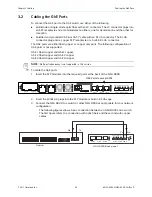
To cable the GbE ports
1.
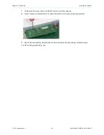
Insert the SFP modules into the required ports at the back of the NSG 9000.
2.
Insert the LC/RJ-45 plugs into the SFP module or built-in RJ-45 cage.
3.
Connect the NSG 9000 to a switch or other NSG 9000 as appropriate for your network
configuration.
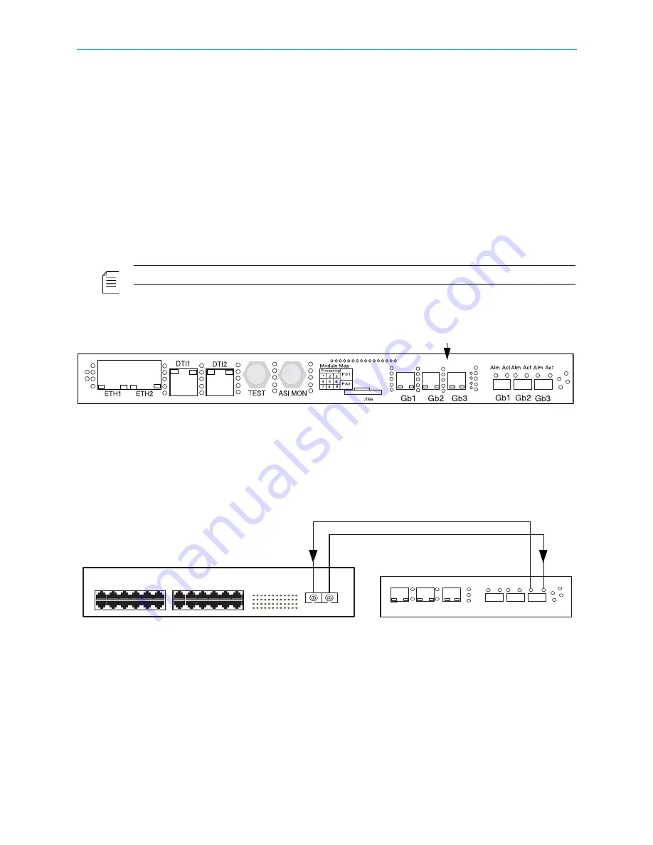
The following figures show a basic connection between an NSG 9000 and a switch.
The first figure refers to a connection with optic fibers and the second with copper
cables:
GbE Ports to accept SFPs
Gb1
Gb2
Gb3
Gb1 Gb2 Gb3
Alm Act Alm Act Alm Act
Tx
Rx
Rx
Tx
NSG 9000 Back panel
Switch


