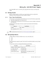
Appendix A Wiring the –48 VDC Power Supply
Connecting the Power Cable to the NSG 9000
© 2011 Harmonic Inc.
38
bNSG 9000 & NSG 9000-3G, Rev D
–Vin
+Vin
GND
5.
Strip up to 0.3 inches (8 mm) of insulation from each of the wires coming from the DC
power source.
Do not strip more than this length from each wire. Stripping more leaves uninsulated wire
exposed outside the DC connector after the assembly is complete.
6.
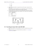
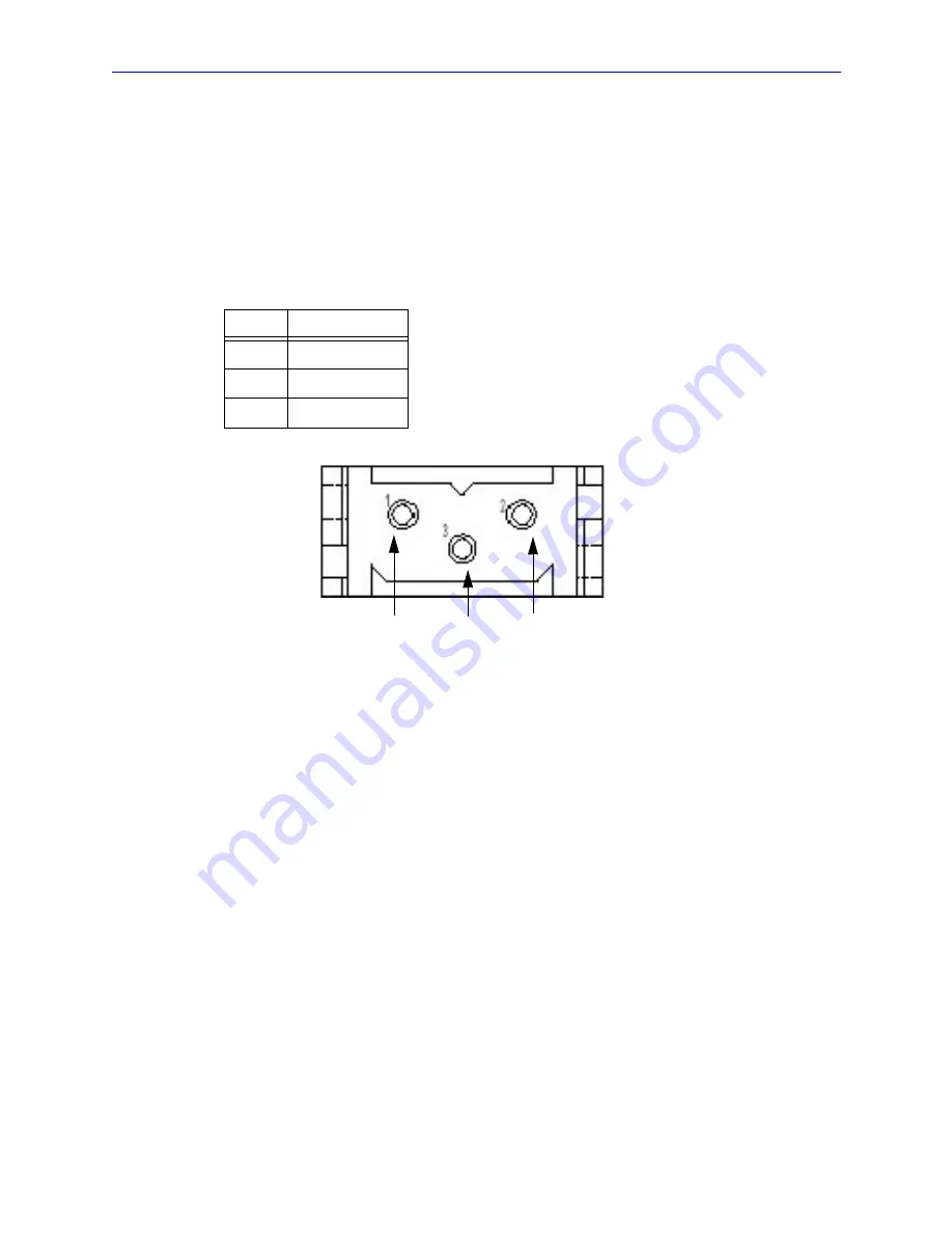
Feed the exposed section of the wires into the matching hole in the DC plug connector
according to the following table and pin-out figure to match wires with the required holes.
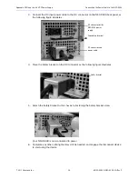
A.4 Connecting the Power Cable to the NSG 9000
1.
Ensure the NSG 9000 is securely installed in a rack and in a Restricted Access Location
only.
2.
Verify that the NSG chassis is properly grounded, as explained in
3.7.1 Grounding the
Mounted Devices
on page 31.
Pin
Signal Name
1
VIN+
2
VIN-
3
Chassis ground
Pin 1: VIN
Pin2: -VIN
Pin 3: chassis
ground

