Installation and Wiring
EIO0000001505 12/2014
107
Safeguarding Function
Overview
The ZARB18• Base Station implement 12 inputs IN7…IN18.
These inputs are dedicated for limit switches to provide a protection to the hoist system.
Description
There are 4 limit switches per axis that allow to:
Stop the motion at minimum mechanical position.
Disable the high speed of the direction when the hoist system is near the minimum position.
Stop the motion at maximum mechanical position.
Disable the high speed of the direction when the hoist system is near the maximum position.
These inputs are associated to motion buttons.
Once a limit switch is opened, the associated motion relay(s) is(are) switched OFF.
You can configure the limit switches with the eXLhoist Configuration Software
.
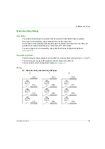
Installation Principle
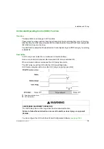
Principle of safeguarding function installation for 1 axis:
1
Mechanical target for limit switch triggering for
stopping
the motion direction
2
Mechanical target for limit switch triggering for
slowing
the motion direction
3
Mechanical target for limit switch triggering for
slowing
the motion direction
4
Mechanical target for limit switch triggering for
stopping
the motion direction
5
Stationary part
6
Mobil part
7
Motion (example: button 1 or 1H)
8
Motion (example: button 2 or 2H)
General Wiring Rules
The I/O and power supply cables should be AWG 16 (cross-sectional conductor area = 1.3 mm
2
).
The I/O and power supply cable lengths should not exceed 20 m (65.6 ft).
For more details, refer to Wiring Best Practices
.
Summary of Contents for eXLhoist
Page 12: ...12 EIO0000001505 12 2014...
Page 34: ...Wireless Remote Control System 34 EIO0000001505 12 2014...
Page 52: ...52 EIO0000001505 12 2014...
Page 146: ...Using The Wireless Remote Control System 146 EIO0000001505 12 2014...
Page 200: ...eXLhoist Configuration Software 200 EIO0000001505 12 2014...
Page 213: ...EIO0000001505 12 2014 213 Harmony eXLhoist EIO0000001505 04 2014 Appendices...
Page 214: ...214 EIO0000001505 12 2014...

