Installation and Wiring
96
EIO0000001505 12/2014
Auxiliary Relays
Base Station wiring:
The description of the relays 13 to 18 depends on the Base Station and Remote Device;
Base Station:
General
Label
Wiring description
Factory setting description
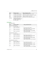
Auxiliary relay 10 CC_10
Common
Selector
Relay 10 is ON when the Selector (button 10) is
in position 1 or 1+2
Relay 11 is ON when the Selector (button 10) is
in position 2 or 1+2
CT_10
Output (NO type)
Auxiliary relay 11 CC_11
Common
CT_11
Output (NO type)
Auxiliary relay 12 CC_12
Common
“Horn” relay
Relay is ON during the start procedure, and for
a configurable duration.
In START mode, the relay is ON as long as the
ON/START/Horn button is pressed.
CT_12
Output (NO type)
Auxiliary relay 13 CC_13
Common
“Radio link” relay
Relay 13 is ON as long as the radio
communication is achieved between the Base
Station and its Remote Device.
CT_13
Output (NO type)
Auxiliary relay 14 CC_14
Common
Relay 14 is ON when button 11 is pressed
CT_14
Output (NO type)
Auxiliary relay 15 CC_15
Common
Relay 15 is ON when button 12 is pressed
CT_15
Output (NO type)
Auxiliary relay 16 CC_16
Common
Relay 16 is ON when button 13 is pressed
CT_16
Output (NO type)
Auxiliary relay 17 CC_17
Common
Relay 17 is ON when button 14 is pressed
CT_17
Output (NO type)
CR_17
Output (NC type)
Auxiliary relay 18 CC_18
Common
Relay 18 is ON when button 15 is pressed
CT_18
Output (NO type)
CR_18
Output (NC type)
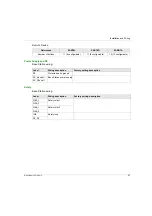
References
ZARB12•
ZARB18•
Motion & auxiliary standard
relays
12 (Q1…Q12)
18 (Q1…Q18)
Summary of Contents for eXLhoist
Page 12: ...12 EIO0000001505 12 2014...
Page 34: ...Wireless Remote Control System 34 EIO0000001505 12 2014...
Page 52: ...52 EIO0000001505 12 2014...
Page 146: ...Using The Wireless Remote Control System 146 EIO0000001505 12 2014...
Page 200: ...eXLhoist Configuration Software 200 EIO0000001505 12 2014...
Page 213: ...EIO0000001505 12 2014 213 Harmony eXLhoist EIO0000001505 04 2014 Appendices...
Page 214: ...214 EIO0000001505 12 2014...

