background image

InstallatIon and operatIon Manual for WInd and sun screen sl400

09/12 

|

 7

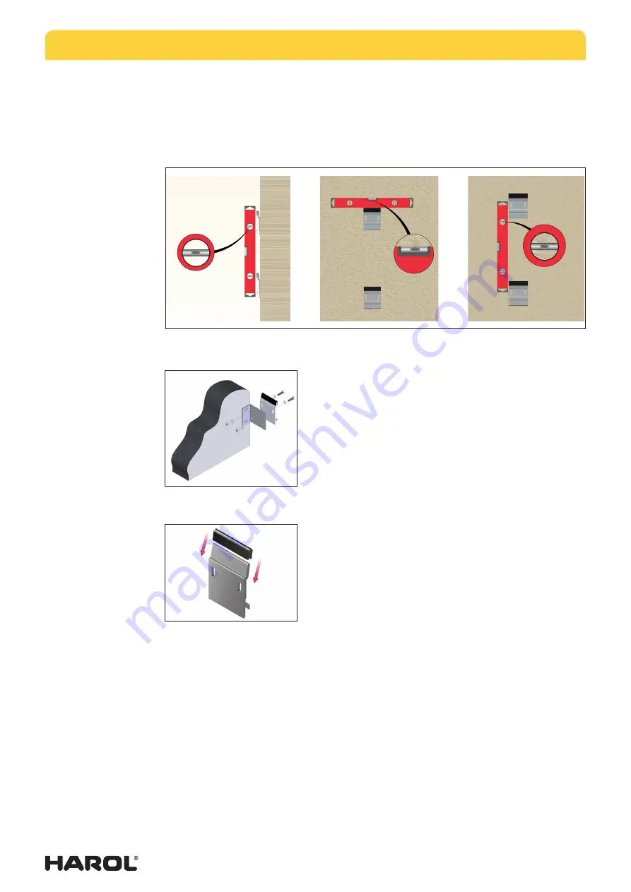
4.6.  alignment of the wall brackets

the two wall brackets must be plumb and level. any irregularities in the mounting surface 
must be compensated. take the time to make sure the screen is positioned perfectly vertically. 
If the mounting surface is of poor quality, we recommend ordering additional brackets. also 
check the distance between the brackets and then tighten all the screws. the mounted 
screen is now ready for further adjustment and alignment of the supporting system.

4.7.  optional mounting of the box (a2638)

Instead of mounting the wall brackets directly on to the wall, 
it is also an option to use a wall console for each wall bracket. 
Here too the choice of fastening materials depends largely 
on the mounting surface and must be assessed by the fitter.

the mounting height of the wall consoles must match the 
distance between the brackets on the box of the SL400. 
once again, it is very important that the wall consoles are 
aligned correctly.

4.8.  Hooking up the box

a damping rubber is placed over each wall bracket. next, the 
SL400 can be hoisted over the brackets and pressed down 
so the screen is sufficiently protected and secure. 

two people are required to attach heavier screens.

4.9.  Installation of the supporting system

a supporting system should be installed at drop distance from the box in order to keep the 
screen in the open position. this supporting system is for hooking up the pull rod.   

there are various ways to do this:

• 

floor assembly (a2642):

 a support pin with ground support plate are anchored on 

to the floor, optionally either a concrete anchor (option a2640) or a ground anchor 
(a2641) can be used. 

• 

wall assembly (a2644):

 a wall mounting block must first be mounted to the wall 

using the appropriate fastening materials. next a short support is fastened to the 
mounting block. 

• 

railing assembly (a2643):

 a wall mounting block must first be mounted to the 

railing using the appropriate fastening materials. next a support pin is fastened to 
the mounting block.

Summary of Contents for SL400

Page 1: ...Installation Operation Manual Wind and Sun Screen SL400 Art no 49013 sun protection shutters doors...

Page 2: ...A2638 7 4 8 Hooking up the box 7 4 9 Installation of the supporting system 7 4 10 Optional installation of a supporting system for wall or railing assembly A2639 8 4 11 Fine tuning of the handgrip he...

Page 3: ...ted in accordance with local requirements and standards All work must be carried out by a trained and experienced member of staff from recognized companies and never by do it yourself fitters or appre...

Page 4: ...cts we strongly advise you to first fit 1 complete awning before fitting the remaining awnings This will help detect any potential faults early on and enable these to be remedied at the lowest possibl...

Page 5: ...rantee card and the table with tensile forces on screws Screws for installation on the existing mounting surface are not included 4 3 Checking the dimensions Measure the length of the box of the SL400...

Page 6: ...5 Mounting height of the wall brackets The height of the mounting brackets on the wall must match the distance between the brackets on the box of the SL400 The housing of the wind and sun screen must...

Page 7: ...on the box of the SL400 Once again it is very important that the wall consoles are aligned correctly 4 8 Hooking up the box A damping rubber is placed over each wall bracket Next the SL400 can be hois...

Page 8: ...stem can be secured to the wall console with the three bolts supplied Depending on the mounting surface the fitter must choose a particular option for securing the console to the wall The mounting hei...

Page 9: ...in the handgrip In order to be able to carry out this action you must first press down the pin on the button 6 2 Closing the screen To close the screen follow the reverse procedure for opening the scr...

Page 10: ...en Please read this manual carefully before operation or maintenance Installation maintenance and repairs must only be carried out by a qualified and experienced technician Malfunctions which can impa...

Page 11: ...e resulting from improper use 7 4 Maintenance To guarantee trouble free use of the SL400 it is prudent to regularly maintain and inspect the screen at least once a year Check for signs of wear or dama...

Page 12: ...ust the height of the assembly brackets for the box 9 General info on fabrics The fabric collection consists of acrylic fabrics and the Soltis range 86 92 or 96 which can be selected from the collecti...

Page 13: ...38 01 11 fax 32 13 31 48 03 de fabrikant Harol NV vertegenwoordigd door Dhr Jan De Lobel kwaliteitsmanager CE Conformity declaration Relevant EC Directives pertaining to machines 2006 42 EC We Harol...

Page 14: ...ation day month year List of components installed drive unit control and safety devices The technical features and performances of the components listed below are documented in the relevant installati...

Page 15: ...09 12 15 Date Description of work Installation start up adjustments check on safety devices repairs alterations Installer s signature Customer s signature...

Page 16: ...n mounting and mounting surface Rain not permitted permitted under the supervision of the user permitted Danger of frost not permitted The following documents are transfered to the user Manual for the...

Page 17: ...ion mounting and mounting surface Rain not permitted permitted under the supervision of the user permitted Danger of frost not permitted The following documents are transfered to the user Manual for t...

Reviews: