background image

HS-3100/3200 Programming Manual

2

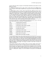
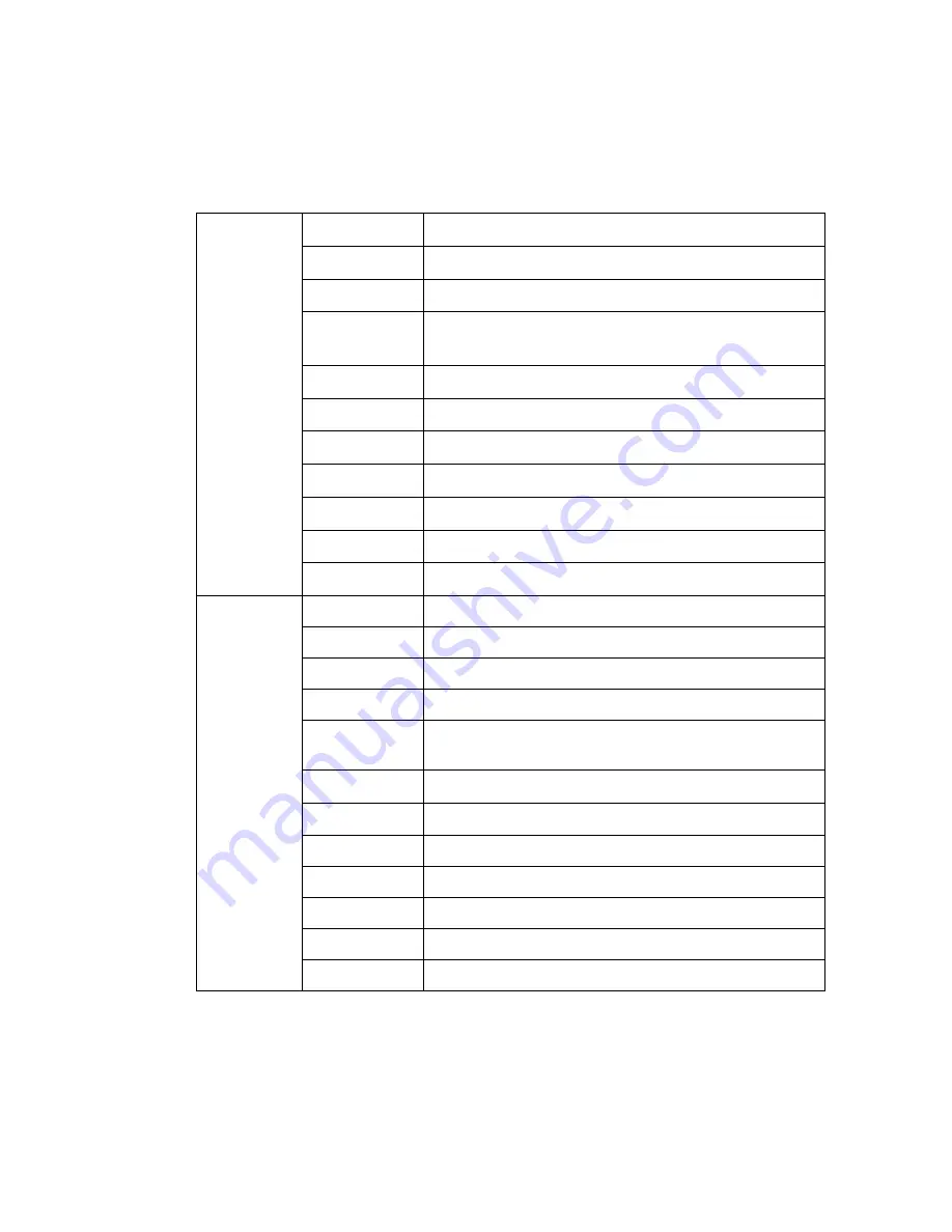
1.3 Addressable Devices

Supported Devices

The HS-3030 can use analog/addressable devices. There are two general types of devices:
sensors and modules. The following devices are supported:

The M500S control module can be used to control a supervised output, such as a bell or strobe
circuit. The control module monitors the circuit wiring and troubles will be reported. The module will
require a separate 24 VDC supply for the controlled circuit. When programming the database in
NP, be sure to program the control module correctly. Choose any “Control (

str

)” other than “Control

(relay)” for the M500S module. The HS-3400 will not operate a control module if the supervised

Modules

M500DM

Dual Input Monitor Module 

M500M

Monitor module, Classes A/B initiating 

M501M

Mini Monitor module, Class B initiating 

M502M

Monitor Module for 2- wire smoke detectors Classes A/B 
initiating

M500S

Control module 

M500R

Relay Module

M500X

Fault isolator module 

IM-10

Intelligent Input Monitor Module


CZ-6

Zone Interface Module

CR-6

Control Module Relay

SC-6

Supervised Control Module

Sensors

1251

Ionization type smoke detector, low profile

1551

Ionization type smoke detector

2251

Photoelectric type smoke detector, low profile

2551

Photoelectric type smoke detector

2251T

Photoelectric type smoke detector c/w heat detector, 
low profile

2551TH

Photoelectric type smoke detector c/w heat detector

2251TMB

Acclimate Photo-Thermal Detector

5251

Fixed temperature detector, low profile

5251H

Fixed high temperature detector

5551

Fixed temperature detector

5251R

Rate of Rise and fixed temperature detector, low profile

5551R

Rate of Rise and fixed temperature detector

Summary of Contents for HS-3100

Page 1: ...Harrington Signal HS 3100 3200 Fire Alarm Control Unit Programming Manual Revision 1 January 2009 Document LT 2001HAR HARRINGTON FIRE ALARM SIGNAL INC...

Page 2: ......

Page 3: ...12 2 6 Panel Window 14 2 7 Outputs Dialog 17 2 8 Options Dialog 19 2 9 Circuits and Devices Windows 28 2 10 Internal Circuits Window 32 2 11 Relate Window 34 2 12 Pushbuttons 35 3 0 LCD Programming 36...

Page 4: ......

Page 5: ...e 11 Dialer Configuration 1 24 Figure 12 Dialer Configuration 2 25 Figure 13 Call Directions 26 Figure 14 Zone Data 27 Figure 15 Dialer Maintenance and Common Reporting Codes 27 Figure 16 Circuits Win...

Page 6: ......

Page 7: ...by the HS2 program otherwise a Database Mismatch trouble condition is generated This condition disables the panel until a correct HS2 program is loaded 5 The database must be completely loaded for it...

Page 8: ...M500M Monitor module Classes A B initiating M501M Mini Monitor module Class B initiating M502M Monitor Module for 2 wire smoke detectors Classes A B initiating M500S Control module M500R Relay Module...

Page 9: ...e The available bases are The sensor LED activates the relay and sounder bases When this LED stays on for more than 10 seconds the base activates This requires that the HS 3030 have the LED mode set t...

Page 10: ...00 always ignores illegal modules Wrong Type U This occurs if the device is not the type expected for the address For example the database lists an address to have a ion smoke detector but a photo smo...

Page 11: ...zero disables this function Once this is done wire the power for the device as shown in Figure 1 A third party power supply must be UL ULC listed compatible power supply suitable for fire application...

Page 12: ...upted delete it and rename its BAK backup file to have a DBA extension This restores the database to the state prior to the last editing session Panel Description The HS 3200 has two Class A or B SLCs...

Page 13: ...n for the entire network If coded bells are required the bell codes are defined for each input individually The following options are available Alert A First Stage alarm activates the selected bells i...

Page 14: ...sounds Steady continuously or uses a Temporal pattern as specified in ANSI S3 41 and ISO 8201 Audible Emergency Evacuation Signal The pattern used s On s Off s On s Off s On 1 s Off repeated Waterflow...

Page 15: ...zer The Pre Alarm Buzzer when enabled will cause a tone to sound when an addressable device is in alarm during the Retard period The tone is a triple beep repeated every second Master ID Master ID def...

Page 16: ...nel is currently defined the Add Panel Box is displayed Switches Displays the Switches Window This window determines which devices are attached to the switches and the timers associated to each switch...

Page 17: ...all 16 possible switches and highlights the current one Select any one to make it the current switch List entries show the message RELATES FOUND for switches that have related devices HH MM Timer The...

Page 18: ...User Guide Verify List Displays the Verify List If there is no Verify List a requester will appear asking whether you wish to perform a verification See section 2 6 5 of the Network Plus User Guide f...

Page 19: ...new group can have any number between 1 and 250 By default the number is the next one available There is no need for the groups to be sequentially numbered or to start at 1 Delete Group This removes...

Page 20: ...ed panel as its Next ID Delete Remove the current panel from the system All programming for that panel will be lost Any of the panel s outputs that are referenced will become invalid and will be remov...

Page 21: ...Outputs Button to show the Outputs Dialog see the Outputs Dialog section which allows for the programming of the Outputs and the relays The Options button displays the Options Dialog see the Options...

Page 22: ...for programming see Figure 10 The LCD check box is located immediately left of the buttons It indicates whether or not the annunciator has an alpha numeric LCD This setting is used by NP only to dete...

Page 23: ...s is located below the Common LED setting It is not displayed for HS 3134 Annunciators This option enables double or disables single the COM 1 network port If both ports are enabled the Next ID text b...

Page 24: ...ow Supv The output sounds when there is any supervisory condition present on the panel Pressing Acknowledge silences the circuit Follow Trouble follow Trbl The output sounds when there is any trouble...

Page 25: ...t or Level 1 Disconnect Disconnect sets the privilege level required for the Disconnect and Test Mode Hot Keys These can be set to Level 1 default or Level 0 If Level 0 is chosen the Disconnect Hot Ke...

Page 26: ...he time between digits is three times this speed The time between rounds is seven times this speed Note that a minimum of three rounds of coded bells is required per NFPA 72 Maintenance Margin Mainten...

Page 27: ...eceived by the panel System Reset System Reset resets part or all of the system The green LED flashes when the system or part of the system can be reset The yellow LED flashes when there are conventio...

Page 28: ...Test Mode Places panel into test mode Press again to return to normal mode The red LED will flash while in test mode This function can be set to Privilege Level 0 or 1 It follows the Disconnect privil...

Page 29: ...iates the general evacuation sequence All bells are activated in Evacuation mode selected function relays are activated and selected releaser circuits are activated and municipal alarm relay is activa...

Page 30: ...ialer will use the third telephone number only if all attempts to communicate to the first telephone number fail If all attempts to communicate to the third number also fail a failure to communicate t...

Page 31: ...s When 40 60 is selected the pulse dialing make break ratio is the 40 60 When 33 67 is selected the pulse dialing make break ratio is 33 67 The Handshake option determines the handshake used for BPS t...

Page 32: ...for a valid initial handshake from the receiver after dialing the programmed telephone number Call Directions The Call Directions dialog see Figure 13 contains the options that determine which teleph...

Page 33: ...Reporting Code Zone Alarm Restoral Reporting Code Trouble Reporting Code Trouble Restoral Reporting Code Supervisory Reporting Code Supervisory Restoral Reporting Code Dialer Maintenance and Common R...

Page 34: ...ddressable input circuits The Devices Window see Figure 17 allows for the defining of addressable devices These two windows are nearly identical Most controls on one are found on the other with the fe...

Page 35: ...B Style B wiring and an end of line resistor This must be chosen for M500DM M501M and M503M modules Monitor Class A This is a standard monitor module using Class A Style D wiring This can be used only...

Page 36: ...inputs operate LEDs only no other outputs are allowed This function type is assigned by NP automatically Message The Message is located in the middle of the top of the window This 3 line by 20 charac...

Page 37: ...to have a monitor module generate a Manual Restart when activated Module Restart must have Non reporting function Pushbuttons The push buttons located on the right hand side are Exit Closes the windo...

Page 38: ...t of all the internal circuits Some of the internal circuits are Internal Circuit 0 General Alarm This is the General Alarm function General Alarm can be received from an annunciator or from an SE 200...

Page 39: ...hbuttons The following push buttons are available List Entries This new feature allows the user to control the information displayed Relevant only lists items applicable to the current version only Al...

Page 40: ...left corner of the window It lists all the panels both Control and Annunciator that are defined in the system along with their panel message The high lighted entry in the list is the one that is being...

Page 41: ...rs or control modules defined Each entry shows the devices s address panel circuit device its state and its device message The states are on for selected and blank for not selected Devices that are no...

Page 42: ...o display other menus show information or request information Menus have a or next to the description of each item Use the arrow keys on the keypad to move the cursor and press Enter to select In Figu...

Page 43: ...is recorded in the archive Calibrate Calibrates the clock so that it keeps correct time Calibration takes 2 to 45 days Waiting longer gives more accurate results The panel functions normally while ca...

Page 44: ...Line 4 Menu Options listed below The menu has the following options OK Return to Program Menu Test Force an immediate battery test Calibrate This function is restricted to Privilege Level 2 This calib...

Page 45: ...input mode OFF Select bypassed devices to be returned to normal operation Each bypassed device is listed in order Select next to keep the bypass on or select OFF to remove the bypass After the last d...

Page 46: ...s required access to the menu is denied This function allows for the manual operation of the relays There are three possible states Automatic state determined by inputs Forced On or Forced Off This mo...

Page 47: ...the length of time the panel will wait before reporting the GRID package off line This can be set from 10 to 255 seconds Disconnect If enabled the Common Disconnect hot key will shut down Port 3 The...

Page 48: ...e Passcodes are four digit numbers in the range 1000 to 9999 Type in the new passcode and press Enter to accept Asterisks are displayed instead of the numbers Clear removes any digits typed If no digi...

Page 49: ...tion a minus sign refers to a restoral or off condition and an equal sign refers to a one time event Archive Alarm List Description A ALARM Alarm B bypass Bypassed Circuit Device C com Comlink D dupl...

Page 50: ...ne Description 0 General Alarm 802 Privilege Level 1 Initiating Circuit 1 81 1st Stage Alarm 2 Initiating Circuit 2 82 2nd Stage Alarm 50 Network Verify 83 Switch 51 Comlink 1 84 Test Mode 52 Comlink...

Page 51: ...ber Comlink 6 Zone 54 Unit ID Number 1 8 MR 2614 9 16 MR 2644 239 City tie 240 MRDL City tie Output Supervision Zone 60 Output Circuit Number Auxiliary Power Supervision Zone 61 Auxiliary Power Circui...

Page 52: ...Reset 010 Common Disconnect 011 General Alarm 016 Switch 1 On 017 Switch 2 On 018 Switch 3 On 019 Switch 4 On 020 Switch 5 On 021 Switch 6 On 022 Switch 7 On 023 Switch 8 On 024 Switch 9 On 025 Switc...

Page 53: ...itch 16 Off 051 Manual Restart Network Reboot Zone 92 Unit ID of panel broadcasting the command Network Reboot Required Who Zone 94 Unit ID of panel generating the Network Reboot Required trouble Netw...

Page 54: ...a few minutes Unfortunately fire alarm control panels need both of these characteristics that is driving a heavy bell load for a relatively short time at the end of a 24 hour standby current drain Thi...

Page 55: ...1 stop bit for communication over the serial port The default baud rate is 9600 bps All screens have a common status line across the top It shows from left to right the current time the current date t...

Page 56: ...o the beginning of the list 10 Miscellaneous Troubles Display a list of all the troubles currently displayed by the STATUS MISC TROUBLES selection from the LCD 11 Output Supervision Shows the current...

Page 57: ...s 0 V Clear counters on screen 19 Port 3 Shows the current status ID frame count and baud rate for the central station communications link A question mark will appear in front of the baud rate when th...

Page 58: ...5 seconds The remote panel stops sending data after 15 minutes Commands id N Display the service terminal for Panel id Esc Disconnect remote connection 69 Network Verify Displays the current status of...

Page 59: ...um Maximum Values 0 P Energize both sets of terminals 1 P Energize only B terminals 2 P Energize only A terminals 85 Alarms For a single circuit shows a grid displaying the current Alarm Early Warning...

Page 60: ...erminals 90 Analog Displays the analog values of 10 consecutive addresses for a single circuit Commands A Display next device address A Display selected device at address 0 M Reset Minimum Maximum Val...

Page 61: ...th date year D Enter the date and year The year may be entered as 00 to 99 in a two digit format or as 1991 to 2090 in a four digit format hours minutes T Set the time hours minutes seconds T Set the...

Page 62: ...hen Dialer Direction Contact ID Auto Rep Codes SIA Auto Rep Codes Zone Supv Rest zone goes into supervisory restore 2 S R AA See Table 4 Zone Alarms Rest zone goes into alarm alarm condition has been...

Page 63: ...r Alarm 24 Hour Non Fire 1 A1 Emergency Panic Alarms 1 51 Gas Detected 1 A2 Fail to Report In 1 2A Panic 1 52 Refrigeration Fire Alarms 1 21 Duress 1 53 Loss of Heat 1 1A Fire Alarm 1 22 Silent 1 54 W...

Page 64: ...Harrington Signal Inc 2519 4th Avenue Moline IL 61265 HARRINGTON FIRE ALARM SIGNAL INC...

Reviews: