background image

HS-3100/3200 Operator’s Manual

7

The 

Main Menu

 has the following selections:

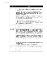
Status:

 Displays the current status of various parts of the panel. The following options are

available:

More:

 Displays the next screen of menu options. When the last screen of the menu is

displayed the next screen will be the first one again.

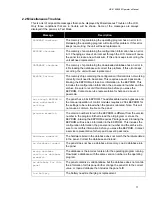
Misc. Trouble:

 Displays any troubles with the bells, releasers, AC power, batteries, etc.,

that are not shown elsewhere. Only sections in trouble will be displayed. Press 

<Enter>

to go to the next screen. See section 2.2 for a list of all possible messages.

Alarm List:

 Displays the Alarm List under manual control. See 

Alarm List

 above, Using

the Keypad.

Addressable:

 This menu has the following options:

Select:

 Displays the current status of a single device. The device address is entered

into the screen saying "circuit or circuit.device". If only a circuit number is entered, the
first programmed device on that circuit will be displayed. If 

<Enter>

 is pressed

without any entry, the first addressable device will be displayed. 

<Clear>

 will remove

any values entered. If there is no value entered, 

<Clear>

 will return to the Status

Menu. If the selected device is not in the database, the next device in the database is
shown.

The display shows the device address in the top left corner and the current condition
codes in the top right corner (see section 2.0 for a description of the condition codes).
The second line shows the headings for the third line, which contains the analog
values sent from the device. Press 

<Enter>

 to view the next device or 

<Clear>

 to

get the address input screen.

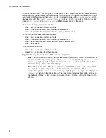
Print Sensors:

 Prints the analog value for every addressable smoke and thermal

detector. This is the value of the detector at the time the command is issued.

Identification:

 Displays a sequence of screens that provide the program and version, the

panel's serial number, database version, etc. Press 

<Enter>

 to go to the next screen.

Print Database:

 This function is restricted to Level 1. Print the current configuration

(values entered through the LCD menu) and downloaded database of the panel to screen
14 of the service terminal.

Print Archive:

 This function is restricted to Level 1. Prints all or part of the history. A

selection menu is presented to select which kinds of events to print. The choices are: All,
Alarms, Supervisory, Trouble, Monitor, Bypass and Non-reporting.

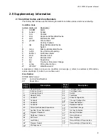
Each entry consists of one or two lines. The information provided on the first line, from the
left, is:

1. Event Number
2. Time (24 Hour Clock)
3. Date (MM/DD/YY Format)
4. Condition Code and Zone Number (see section 2.1)
5. Description

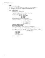
A second line will be printed for addressable devices if a message exists in the database.

This history is sent to the service terminal port  if  Screen  14  is  active.  Screen  14  of  the
service terminal is a copy of all items sent to the printer port.

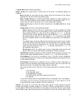
Archive:

 The archive is a list of the last 1000 events (approx.). These include all signals,

programming changes, time/date changes, etc., that have occurred. Test signals may or may not
be recorded but "Test On" and "Test Off" are. The archive is not lost when there is a loss of both
AC and battery power. Each entry includes a short description of the event, and the date and time

Summary of Contents for HS-3200

Page 1: ...Harrington Signal HS 3100 3200 Fire Alarm Control Unit Operator s Manual Revision B Document LT 2002HAR HARRINGTON FIRE ALARM SIGNAL INC ...

Page 2: ...5 by Harrington Inc No part of this publication may be reproduced transmitted transcribed stored in a retrieval system or translated into any language or computer language in any form by any means electronic magnetic optical chemical manual or otherwise without the prior consent of Harrington Inc Harrington Signal Inc 2519 4th Ave Moline Illinois 51265 ...

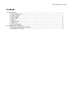
Page 3: ...on 1 1 1 Power Up Sequence 1 1 2 Types of Inputs 1 1 3 Status Display 2 1 4 Zone LEDs 2 1 5 Buzzer 2 1 6 Operator Keys 3 1 7 Alarm List 5 1 8 LCD and Keypad 6 2 0 Supplementary Information 9 2 1 Condition Codes and Zone Numbers 9 2 2 Miscellaneous Troubles 11 ...

Page 4: ...HS 3100 3200 Operator s Manual ii ...

Page 5: ...vate bells and or strobes as well as an LED They can optionally operate relays and control modules on a network panel This type displays WATERFLOW in the Alarm List Through programming Waterflow type alarms can make the bell circuits they activate to be non silenceable Supervisory This type of input is for items such as Shut Off valves and Pressure sensors for sprinkler systems They are required t...

Page 6: ...and keypad see Section 1 8 below to determine the exact condition A new condition is shown by a flashing LED After the Acknowledge button see Section 1 6 below has been pressed the LED will be lit steadily Note If the buzzer is sounding on the panel Acknowledge will silence the buzzer but not latch the LEDs Press Acknowledge again to latch the LEDs Each set of zone LEDs is programmed via the datab...

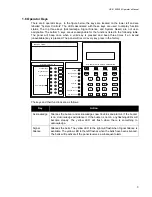
Page 7: ... and their functions are as follows Key Action Acknowledge Silences the buzzer and acknowledges new troubles and alarms If the buzzer is on Acknowledge will silence it If the buzzer is not on any flashing LEDs will become steady The yellow LED will flash when there is something to acknowledge Signal Silence Silences the bells The yellow LED to the right will flash when Signal Silence is available ...

Page 8: ...the panel into test mode Press again to return to normal mode The yellow LED will flash while in test mode This function can be set to Privilege Level 0 or 1 It follows the Disconnect privilege level set in MHI During test mode the panel annunciator becomes non latching for the zone s under test The common indicators bells relays are not activated and no signal is sent out of Port 3 Test signals c...

Page 9: ...ries are provided Display can begin with Common Disconnect This function is configurable It can be programmed to disable the relays or to disable a City Tie module HS3CTYB When an HS3CTYB module is disconnected a trouble will be reported to the city and then any subsequent signals will not be reported until the card is re enabled When the relays are disabled the yellow LED flashes while the relays...

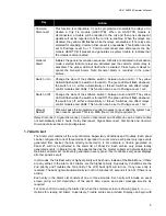
Page 10: ... turn off in 5 minutes 30 seconds if no AC if there is no activity Pressing the Lamp Test button causes all panel LEDs to flash Pressing Lamp Test again will stop the flashing Timeout for this option is 30 seconds The LCD will show Lamp Test active Information is presented to the user through a series of menus and information screens The menus present options to display other menus show informatio...

Page 11: ...the device Press Enter to view the next device or Clear to get the address input screen Print Sensors Prints the analog value for every addressable smoke and thermal detector This is the value of the detector at the time the command is issued Identification Displays a sequence of screens that provide the program and version the panel s serial number database version etc Press Enter to go to the ne...

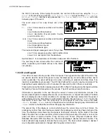
Page 12: ...e Number see section 2 1 Line 3 description of event alarm trouble ground restore etc Line 4 device type The second screen shows Line 1 time sequence number and date Lines 2 to 4 description from the database Program Displays the Clock Menu This menu has 2 options Date View or change the date The date is entered in MM DD YY format Each section of the date must be separated by a dot Press Enter to ...

Page 13: ...us sign refers to a new or on condition a minus sign refers to a restoral or off condition and an equal sign refers to a one time event Zone Number PPP ZZ SSS Format PPP Control Panel Number ZZ Panel Zone Panel Zone Description Panel Zone Description 0 General Alarm 81 1st Stage Alarm 1 Initiating Circuit 1 82 2nd Stage Alarm 2 Initiating Circuit 2 83 Switch 50 Network Verify 84 Test Mode 51 Comli...

Page 14: ...240 HS3DL Output Supervision Zone 60 Output Circuit Number Program Re start Zone 69 000 Power On Hard reboot 001 Watchdog 002 Clock Monitor 003 Illegal Instruction 004 Unused Interrupt 005 Orphan Interrupt Privilege Level Zone 80 Level Set Switch Zone 83 Switch Number Hot Key Activation Zone 90 Function Number of the Hot key pressed Network Reboot Zone 92 Unit ID of panel broadcasting the command ...

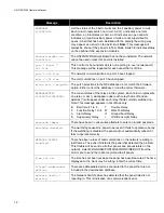
Page 15: ... Contact a service representative for help and a Level 9 passcode not enough EEPROM to save addressable settings The panel has a 64k EEPROM The addressable device bypasses and the manual operation of control modules requires a 256k EEPROM for the settings to be retained when the panel is rebooted Note This will not cause a common trouble on the panel program mismatch The version number stored in t...

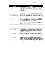
Page 16: ... Each column represents one relay A dot will appear under each relay that is off and an asterisk will appear under each relay that is currently switched on Note This message appears in Test Mode only B Bell Circuit 1 to 8 T Trouble Relay F Function Relay 1 to 4 W Walk Test Relay A Alarm Relay G Ground Fault Relay S Supervisory Relay L LCD Back Light Relay passcode tamper There have been 3 consecut...

Page 17: ...e forced select PROGRAM RELAYS MODES INDIVIDUAL from the LCD menu manual switches One or more switches with timers have been forced either on or off This is not shown for switches that do not have timers To view which switches are forced select PROGRAM SWITCHES INDIVIDUAL from the LCD menu MEMORY OVERFLOW An event happened that caused an out of memory condition This means that an event has been lo...

Page 18: ......

Page 19: ......

Page 20: ...Harrington Signal Inc 2519 4th Avenue Moline IL 61265 HARRINGTON FIRE ALARM SIGNAL INC ...

Reviews: