HARRIS INTERTYPE GATES STEREO 80, Technical Manual
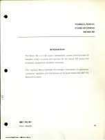
The HARRIS INTERTYPE GATES STEREO 80 is a high-quality audio system that offers exceptional stereo sound. To maximize your experience with this product, be sure to get the comprehensive Technical Manual. You can easily download this invaluable manual for free at 88.208.23.73:8080, providing everything you need to fully understand and optimize your stereo system.
Share
Download

Reviews:
No comments
Related manuals for GATES STEREO 80

500 Series
Brand: OceanAudio Pages: 2

MS-100
Brand: MAKINEX Pages: 16

4010
Brand: ZETRON Pages: 123

3
Brand: Teac Pages: 22

KGS
Brand: Danfoss Pages: 10

Powerhead PA Mixer
Brand: KAM Pages: 4

CL3
Brand: Yamaha Pages: 65

CL3
Brand: Yamaha Pages: 401

TM300
Brand: Samson Pages: 58

PYD1030
Brand: Pyle Pages: 8

AG-HMX100
Brand: Panasonic Pages: 37

Ramsa WR-DA7 mkII
Brand: Panasonic Pages: 63

6100 Series
Brand: Tapco Pages: 25

MW10
Brand: Yamaha Pages: 36

Apollo
Brand: Calrec Pages: 124

CD100
Brand: Laney Pages: 20

40 Series
Brand: Bailey Pages: 103

Xenon
Brand: DAPAudio Pages: 18


