APEX
™
Exciter Incorporating FLO
™
Technology
Navigating the LCD Display Screens
Details of the Exciter Status Screens
Page: 3-8
888-2604-001
03/08/07
WARNING: Disconnect primary power prior to servicing.
3.4
Details of the Exciter Status Screens
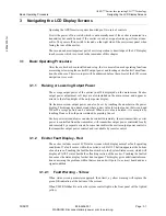
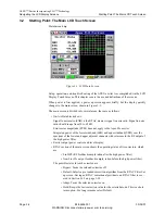
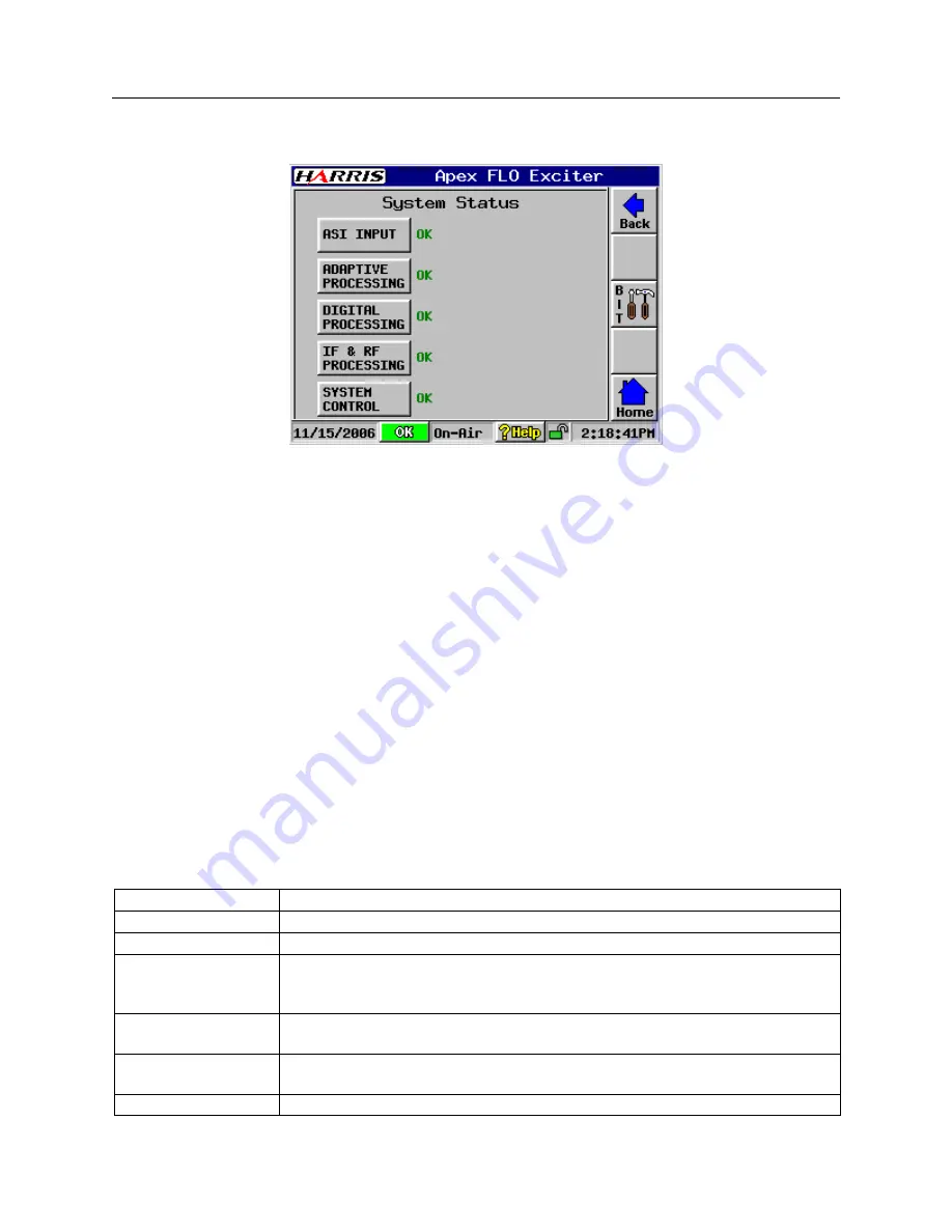
SystemStatus.bmp
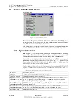
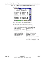
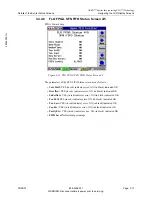
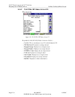
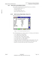
Figure 3-5 System Status Screen
This section provides pictures and details of the Exciter Status screen, shown in Figure 3-5,
and its sub screens. The sub screens give the status of selected control areas or PC boards,
some of the sub screens include diagnostics screens.
If the Diagnostics Setup on the Exciter System Setup screen is locked, all diagnostics
functions will be locked, and their various screen selection values will be greyed out.
3.4.1
System Status Screen
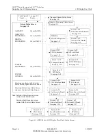
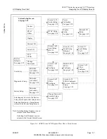
Refer to Figure 3-5. The System Status screen serves two purposes. First, it provides a
general status of five items, and secondly it provides access to many sub screens which
give additional status information about selected circuit boards within the exciter.
Five small boxes are displayed within the System Status screen. These boxes represent
circuit boards or control areas within the exciter, see names in Table 3-1. The general status
of each section (OK or FAULT) is displayed to the right of each box. Touching any of the
boxes brings up the status screen for that selection.
Five hardware switches on the exciter front panel (to the immediate right of the LCD
display) provide short cuts which leads directly to the five status areas listed in Table 3-1.
Table 3-1 System Status Screen Circuit Board Names
Box Name
Circuit Board Name
ASI Input
ASI input status, FPGA Modulator board, see page 3-9
Adaptive Processing
Adaptive Precorrector board, see page 3-9
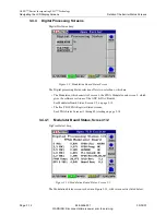
Digital Processing
(shown in two screens)
Digital Processing Status on page 3-12,
From there two choices:
First
Modulator on
page 3-12, and ADC or DAC boards page 3-12.
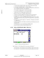
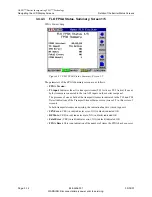
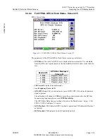
Second
the FLO FPGA Registers
Screens (1 through 5) starting on page 3-14.
IF and RF Processing
(shown in four screens)
UDC Interface on page 3-19, PLL on page 3-20, Up Converter on page 3-21 and Down
Converter on page 3-23
System Control
(shown in four screens)
Controller board on page 3-26, External I/O board on page 3-27, CAN Bus on
page 3-30, Front Panel Board Status page 3-30, and GPS Status page 3-31.
BIT (built in tests)
Built In Tests on page 3-32

