Section 4
♦
Operating the CMN-41
CMN-41 Series Installation and Operation Handbook
53
Copyright © 2009, Harris Corporation
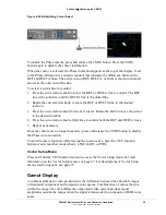
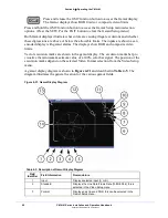
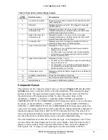
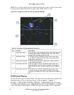
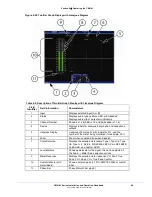
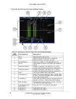
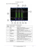
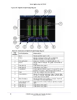
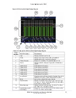
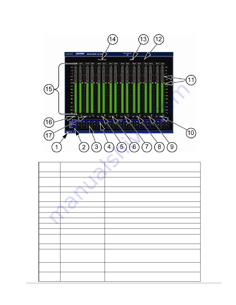
Figure 4-33. Sixteen Bar Graph Display Diagram
Table 4-13. Description of Sixteen Bar Graph Display Diagram
Field
Identifier
Field Information
Nomenclature
1
Input
Displays selected input (A or B)
2
Status
Displays audio type as Mute, AES, or Embedded
Displays audio clip or mute alarm indicators
3
Channel Number
Shown as 1-16 (AES is 1-2 and Embedded is 1-16)
4
Device
Displays labels for lissajous, bar graphs, and headphone
outputs
5
Phase Bar (3)
Phase Meter of bar graph 3
6
Phase Bar (4)
Phase Meter of bar graph 4
7
Phase Bar (5)
Phase Meter of bar graph 5
8
Phase Bar (6)
Phase Meter of bar graph 6
9
Phase Bar (7)
Phase Meter of bar graph 7
10
Phase Bar (8)
Phase Meter of bar graph 8
11
Level Markers
Shows peak and reference levels for the signal; this can be
adjusted in the Audio
→
Meter Setup selection options
12
Zoom
Zoom when enabled; blank when disabled
13
Scale Selection
Displays the selected meter scale: Type I, Type IIa, Type
IIb, Type I + 8, Nordic, DIN 45406, dBFS, Zero REF dBFS,
Custom dB, and Custom dBFS
14
Meter Response
Displays selected meter response: VU, Peak, True Peak,
VU + Peak, VU + True Peak, Custom
15 Audio
Graticule
(with
meter labels)
Shown as L1, R1, L2, R2, L3, R3, L4, R4, L5, R5, L6, R6,
L7, R7, L8, or R8 (or Custom label)

