Harris Corporation
Constellation®
LIST OF
FIGURES
L
IST
OF
F
IGURES
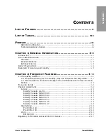
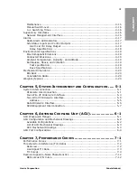
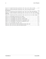
Figure 3-1: Traffic Plan Example for 3xDS3 (2xDS3+28 DS1) ................................ 3-3
Figure 3-2: Multiplexer configuration for a radio terminal ...................................... 3-5
Figure 3-3: Multiplexer configuration for a radio-to-radio repeater .......................... 3-6
Figure 3-4: Multiplexer configuration for a dual radio terminal ............................... 3-6
Figure 3-5: Constellation radio terminal, DS3 interface ......................................... 3-7
Figure 3-6: 28 DS1 to DS3 application ................................................................ 3-7
Figure 3-7: 28 DS1 to repeater to DS3 application ............................................... 3-8
Figure 3-8: 4xDS3 to 4xDS3 configuration .......................................................... 3-9
Figure 3-9: 3xDS3 to 3xDS3 configuration .......................................................... 3-9
Figure 3-10: 3xDS3 to 3xDS3 back-to-back terminals ......................................... 3-10
Figure 3-11: 3xDS3 configured as a 2xDS3 + 28DS1 configuration ....................... 3-10
Figure 3-12: 3xDS3 configured as 2xDS3 + 28DS1 back-to-back terminals ........... 3-11
Figure 3-13: 3(4)xDS3 configured as 2(3)xDS3 + 28DS1 terminal, ADM repeater, and
3(4)xD3 terminal ........................................................................................... 3-11
Figure 3-14: OC-3/STM-1 to OC-3/STM-1 Configuration ...................................... 3-12
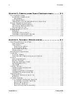
Figure 4-1: Battery voltage noise limit ................................................................ 4-2
Figure 6-1: ACU, nonprotected (top view), mechanical drawing .............................. 6-3
Figure 6-2: ACU, nonprotected (front view), mechanical drawing ............................ 6-4
Figure 6-3: ACU, hot-standby (top view), mechanical drawing ............................... 6-4
Figure 6-4: ACU, hot-standby (front view), mechanical drawing ............................. 6-5
Figure 6-5: ACU, hot-standby Transmitters, space-diversity Receivers (top view),
mechanical drawing ......................................................................................... 6-5
Figure 6-6: ACU, hot-standby Transmitters, space-diversity Receivers (front view),
mechanical drawing ......................................................................................... 6-6
Figure 6-8: ACU, hot-standby/frequency-diversity 2-antenna (T/R, T/R) (front view),
mechanical drawing ......................................................................................... 6-7
Figure 6-9: ACU, repeater/dual terminal, mechanical drawing ................................ 6-8
Figure 7-1: Typical threshold-to-interference (T/I) curve (6 GHz and 7/8 GHz, 8 DS1) 7-
4
Figure 7-2: Typical threshold-to-interference (T/I) curve (10/11 GHz, 8 DS1) .......... 7-5
Figure 7-3: Typical threshold-to-interference (T/I) curve (6 GHz and 7/8 GHz, 16 DS1) .
Summary of Contents for Constellation
Page 1: ...Microwave Digital Radios Constellation Systems Application P N SAI 112874 E09...
Page 2: ......
Page 3: ...CONSTELLATION MICROWAVE RADIO SYSTEM APPLICATION MANUAL PART NO SAI 112874 E09 JANUARY 2006...
Page 4: ...Constellation January 2006...
Page 18: ...Constellation January 2006 xii Preface...
Page 20: ...Constellation January 2006 xiv Preface...
Page 24: ...Constellation January 2006 1 4 General Information...
Page 92: ...Constellation January 2006 6 10 Antenna Coupling Unit ACU...
Page 110: ...Constellation January 2006 7 18 Performance Curves...
Page 124: ...Constellation January 2006 Index 6...
Page 125: ......
Page 126: ...6 0LFURZDYH RPPXQLFDWLRQV LYLVLRQ DYLV ULYH 0RUULVYLOOH 1 86 ZZZ KDUULV FRP 86 DQDGD RUOGZLGH...

