background image

Harris Corporation 

Constellation®

Configurations 


3-7

CONSTELLATION 

RADIO 

CONFIGURATIONS

Constellation DS3 Interface

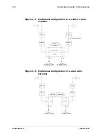
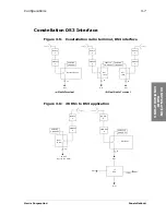
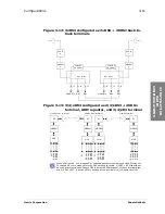
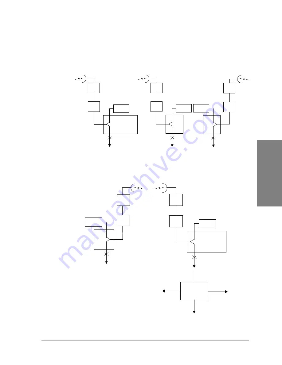
Figure 3-5: Constellation radio terminal, DS3 interface

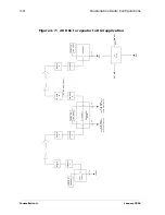
Figure 3-6: 28 DS1 to DS3 application

RADIO

A

MODEM

A

DS3 INTERFACE

JF

DS3

(a) Radio Terminal

RADIO

A

MODEM

A

DS3

JF

DS3

(b) Dual Radio Terminal

RADIO

A

MODEM

A

JF

DS3

INTF

DS3
INTF

SERVICE

CHANNEL

SERVICE

CHANNEL

SERVICE

CHANNEL

RADIO

A

MODEM

A

DS3 HLM

JF

DS3

SERVICE

CHANNEL

RADIO

A

MODEM

A

JF

1-28 DS1s

HLM

SERVICE

CHANNEL

(in group of 4 DS1s)

28 DS1

3/1

DCS

DS3

DS1

DS3

(CPE)

Summary of Contents for Constellation

Page 1: ...Microwave Digital Radios Constellation Systems Application P N SAI 112874 E09...

Page 2: ......

Page 3: ...CONSTELLATION MICROWAVE RADIO SYSTEM APPLICATION MANUAL PART NO SAI 112874 E09 JANUARY 2006...

Page 4: ...Constellation January 2006...

Page 5: ...Constellation FARSCAN and STARVIEW are trademarks of HARRIS CORPORATION Data subject to change without notice Harris Corporation Microwave Communications Division 637 Davis Drive Morrisville NC 27560...

Page 6: ...uppl mentaire pourraient causer des blessures ou endommager l quipement et peut entra ner l annulation de sa garantie WARNUNG Die an diesen Ger ten gemachte Einstellungen und oder nderungen welche nic...

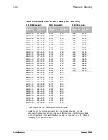
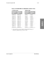
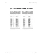
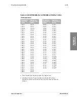
Page 7: ...Frequency Selection 2 1 1 1 Frequency Spacing for Hot standby HS and Nonprotected NP Radios 2 1 1 1 Intermodulation Products for Multiple HS or NP Radios with Common Antenna Feedline 2 2 Frequency Ba...

Page 8: ...Consumption 4 1 Power Source 4 2 Power Source Voltage 4 2 Power Source Noise 4 2 Built in Radio Fuse Panel 4 2 Circuit Breakers 4 3 RF Performance Specifications 4 3 Transmitter 4 10 Frequency Stabili...

Page 9: ...A Rack 4 20 Constellation Radio 4 20 Weights Typical 4 20 CHAPTER 5 SYSTEM INTERCONNECT AND CONFIGURATION 5 1 System Interconnection 5 1 Orderwire Interconnection 5 1 Four Wire VF Orderwire Interface...

Page 10: ...Constellation January 2006 iv Contents BER versus RSL Dynamic Range 7 17 APPENDIX A RACK PROFILES A 1 19 inch Rack Frame A 1 APPENDIX B GLOSSARY B 1 INDEX...

Page 11: ...al 3 11 Figure 3 14 OC 3 STM 1 to OC 3 STM 1 Configuration 3 12 Figure 4 1 Battery voltage noise limit 4 2 Figure 6 1 ACU nonprotected top view mechanical drawing 6 3 Figure 6 2 ACU nonprotected front...

Page 12: ...55 Mbit s 128 TCM 7 10 Figure 7 8 Typical threshold to interference T I curve 6 7 8 10 11 GHz 4DS3 7 11 Figure 7 9 Typical BER versus C N curve 8 DS1 7 12 Figure 7 10 Typical BER versus C N curve 16 D...

Page 13: ...5 MHz to 8500 MHz ITU R 386 5 A3 2 10 Table 2 14 5925 MHz to 6425 MHz FCC Part 101 2 11 Table 2 15 6525 MHz to 6875 MHz FCC Part 101 2 12 Table 2 16 10550 MHz to 10680 MHz FCC Part 101 2 13 Table 2 17...

Page 14: ...nection 5 7 Table 6 1 Standard flange specifications 6 1 Table 6 2 Spacer adapter height standard other interfaces available 6 1 Table 6 3 Available ACU configurations 6 2 Table 6 4 X dimension from f...

Page 15: ...omer equipment problems quickly and accurately in a timely manner Customers who completed product training given by Harris Microwave Communications Division and are equipped with proper test equipment...

Page 16: ...912 Email wotero harris com Harris do Brasil Edif cio STADIUM Al Rio Negro 1030 Conjuntos 202 204 206 CEP 06454 000 Alphaville Barueri SP Phone 55 11 4197 3000 FAX 55 11 4197 3001 Email crcbraz harris...

Page 17: ...ommunications Shenzhen R3 B2 High Tech Industrial Park Nanshan District Shenzhen 518057 The People s Republic of China Phone 86 755 663 7928 Fax 86 755 663 7048 Trisilco Folec 36 1 Jalan PJU 8 5B Perd...

Page 18: ...Constellation January 2006 xii Preface...

Page 19: ...our customer service department By Fax 514 685 4580 By email crcmtl harris com By mail Harris Corporation Microwave Communications Division 3 Hotel de Ville Dollard des Ormeaux Quebec CANADA H9B3G4 PL...

Page 20: ...Constellation January 2006 xiv Preface...

Page 21: ...quipment The Constellation Radio Constellation radios make up one of Harris families of high quality transmission equipment The radios feature multiple capacities and frequency bands upgrade capabilit...

Page 22: ...d alarm inputs ACU expansion port Standard interfaces for OEM equipment Optional Features High System Gain Option for OC3 3xDS3 2xDS3 28xDS1 4xDS3 3xDS3 28xDS1 High System Gain Option for 16xDS1 28xDS...

Page 23: ...rris reserves the right to make changes in circuit design specifications services and other information at any time without prior notice Harris does not assume responsibility or liability arising out...

Page 24: ...Constellation January 2006 1 4 General Information...

Page 25: ...y of the listed receive frequencies provided the minimum T to R separation is maintained It is recommended that any unlisted frequency be verified by Harris MCD Table 2 1 Frequency spacing Minimum Spa...

Page 26: ...on that antenna feeder Note that all possible combinations must be taken into account for example 2A B 2B D A B C C D B and so forth Frequency Bands Constellation radios are available in 6 7 8 10 and...

Page 27: ...A4 Rec 386 5 A3 7110 to 7750 7425 to 7725 7425 to 7900 7725 to 8275 28 28 28 29 65 Rec 385 6 A3 Rec 385 6 A1 Rec 385 6 A4 Rec 386 4 A1 Table 2 4 Frequency band U S A Frequency Band MHz Channel Bandwid...

Page 28: ...Bandwidth 5 MHz Bandwidth 10 MHz Bandwidth Transmit Receive MHz Receive Transmit MHz Transmit Receive MHz Receive Transmit MHz Transmit Receive MHz Receive Transmit MHz 5851 75 5885 25 5852 825 5886 1...

Page 29: ...74 85 6226 89 5960 02 6212 06 6004 50 6256 54 5989 67 6241 71 6034 15 6286 19 6019 32 6271 36 6063 80 6315 84 6048 97 6301 01 6093 45 6345 49 6078 62 6330 66 6123 10 6375 14 6108 27 6360 31 6152 75 64...

Page 30: ...5 6925 90 MHz Tx Rx Spacing 6595 6685 6605 6695 6615 6705 6625 6715 6635 6725 6645 6735 6655 6745 6665 6755 6675 6765 Table 2 7 6425 MHz to 6930 MHz Industry Canada SRSP 306 4 Continued 10 MHz Bandwid...

Page 31: ...7152 5 7327 5 7452 5 7602 5 7180 7355 7157 5 7332 5 7457 5 7607 5 7190 7365 7162 5 7337 5 7462 5 7612 5 7200 7375 7167 5 7342 5 7467 5 7617 5 7210 7385 7172 5 7347 5 7472 5 7622 5 7220 7395 7177 5 735...

Page 32: ...eceive Transmit MHz Transmit Receive MHz Receive Transmit MHz 7730 8030 7740 8040 7740 8040 7770 8070 7750 8050 7800 8100 7760 8060 7830 8130 7770 8070 7860 8160 7780 8080 7890 8190 7790 8090 7920 822...

Page 33: ...ansmit Receive MHz Receive Transmit MHz 10552 5 10617 5 10557 5 10622 5 10562 5 10627 5 10567 5 10632 5 10572 5 10637 5 10577 5 10642 5 10582 5 10647 5 10587 5 10652 5 10592 5 10657 5 Table 2 11 10700...

Page 34: ...smit Receive MHz Receive Transmit MHz 7435 7680 7449 7694 7463 7708 7477 7722 7491 7736 7505 7750 7519 7764 7533 7778 7547 7792 7561 7806 7575 7820 7589 7834 7603 7848 7617 7862 7631 7876 7645 7890 Ta...

Page 35: ...70 6130 51 6382 55 5974 85 6226 89 6063 80 6315 84 6136 072 6388 112 6135 45 6387 49 5984 73 6236 77 6093 45 6345 49 6141 014 6393 054 6140 40 6392 44 5994 62 6246 66 6123 10b 6375 14b 6145 955 6397 9...

Page 36: ...625 6770 625 6610 6770 6655 6815 6615 625 6775 625 6615 6775 6665 6825 6620 625 6780 625 6620 6780 6675 6835 6625 625 6785 625 6625 6785 6685 6845 6630 625 6790 625 6630 6790 6695 6855 6635 625 6795 6...

Page 37: ...558 125 10623 125 10557 5 10622 5 10563 125 10628 125 10562 5 10627 5 10568 125 10633 125 10567 5a a These frequencies are also available for DEMS stations licensed in operation or applied for prior t...

Page 38: ...25 11628 125 11137 5 11627 5 11143 125 11633 125 11142 5 11632 5 11148 125 11638 125 11147 5 11637 5 11153 125 11643 125 11152 5 11642 5 11158 125 11648 125 11157 5 11647 5 11163 125 11653 125 11162 5...

Page 39: ...tems and should be used only if all other channels are blocked 10985 11475 10735 11225 10995 11485 10745 11235 11005 11495 10755 11245 11015 11505 10765 11255 11025 11515 10775 11265 11035 11525 10785...

Page 40: ...85 10935 11425 10975 11465 11015 11505 11055 11545 11095 11585 11135a 11625 11175 11665 a Alternate channels These channels are set aside for narrow bandwidth systems and should be used only if all ot...

Page 41: ...128 QAM Harris Corp HRS CX 06G16D1 28DS1 0 0003 10M0D7W 47 000 64 QAM Harris Corp HRS CX 06G28D1 155M 0 0003 30M0D7W 172 560 128 TCM Harris Corp HRS CX 06G155M 4DS3 0 0003 30M0D7W 197 419 256 TCM Har...

Page 42: ...orp HRS CX 10G16D1 16DS1 High Gain 0 0003 5M0D7W 28 614 128 TCM Harris Corp HRS CX 10G16D1 H Constellation 11 GHz 8DS1 0 0003 3M75D7W 13 800 32 QAM Harris Corp HRS CX 11G08D1 16DS1 0 0003 5M0D7W 27 10...

Page 43: ...o supports an add drop of up to 16 DS1 signals from each direction The DS1 signals must be dropped in groups of four The high capacity Constellation radio is not available in a repeater configuration...

Page 44: ...s depending on whether the OEM multiplexer is protected At back to back terminals when the receive DS3 signals are passed directly from radio to radio without passing through external terminating equi...

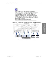
Page 45: ...Traffic Plan Example for 3xDS3 2xDS3 28 DS1 Back to Back Terminals Repeater Terminal Terminal Drop 4 DS1 s DS2 1 from Site 1 DS3 3 For NP add 1 M12 card For MHSB also add Protection M12 and 7 filler c...

Page 46: ...s network and for provisioning the network elements The Keypad allows the customer to quickly configure a system or diagnose a trouble on a hop In place of a Keypad the customer can connect a terminal...

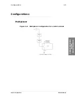
Page 47: ...onstellation Configurations 3 5 CONSTELLATION RADIO CONFIGURATIONS Configurations Multiplexer Figure 3 2 Multiplexer configuration for a radio terminal RADIO A MODEM A MUX JF 1 28 DS1s in group of 4 D...

Page 48: ...nfiguration for a dual radio terminal RADIO A MODEM A MUX JF 1 16 DS1s in group of 4 DS1s RADIO B MODEM B JF 1 16 DS1s 8 to 28 DS1s SERVICE CHANNEL EXPANSION SHELF in group of 4 DS1s to any M12 slot 1...

Page 49: ...igure 3 6 28 DS1 to DS3 application RADIO A MODEM A DS3 INTERFACE JF DS3 a Radio Terminal RADIO A MODEM A DS3 JF DS3 b Dual Radio Terminal RADIO A MODEM A JF DS3 INTF DS3 INTF SERVICE CHANNEL SERVICE...

Page 50: ...IO A MODEM A DS3 HLM JF DS3 SERVICE CHANNEL RADIO A MODEM A JF 28 DS1s HLM SERVICE CHANNEL 28 DS1 3 1 DCS DS3 DS1 DS3 CPE RADIO A MODEM A HLM 28 DS1 JF 0 16 DS1s in group of 4 DS1s RADIO B MODEM B JF...

Page 51: ...xDS3 configuration Figure 3 9 3xDS3 to 3xDS3 configuration RADIO A MODEM A DS3 HLM JF DS3 1 SERVICE CHANNEL JF DS3 2 JF DS3 4 RADIO A MODEM A DS3 HLM JF DS3 4 SERVICE CHANNEL JF DS3 2 JF DS3 1 DS3 3 J...

Page 52: ...DS1 configuration RADIO A MODEM A DS3 HLM JF DS3 1 SERVICE CHANNEL JF DS3 2 JF DS3 3 RADIO A MODEM A DS3 HLM JF DS3 3 SERVICE CHANNEL JF DS3 2 JF DS3 1 If no DS3 access is planned or required at this...

Page 53: ...F DS3 JF 4 28 DS1s MUX MODEM 28 T DS3 2 RF RF RF RF 2 3DS3 28T Terminal 3 4DS3 ADM Repeater 3 4DS3 Terminal MUX MODEM MUX MODEM MUX MODEM DS3 2 DS3 2 DS3 3 DS3 3 DS3 3 DS3 3 DS3 4 DS3 4 DS3 4 DS3 4 DS...

Page 54: ...th all repeaters at least one repeater needs to be set for Source timing In large systems the HLM cards in repeater configurations need to be set for Source timing after 15 consecutive repeaters to cl...

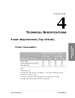
Page 55: ...wer consumption 2 x terminal consumption less 5 3 Add 3 5 W for each M12 Unit 4 DS3 3DS3 4DS3 and 155 Optical Electrical use back to back terminals 5 For high system gain options add 4W per transmitte...

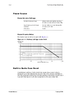
Page 56: ...ower only to the various assemblies in the radio equipment shelf Harris recommends that external fuse panel be used to provide fused power to all other equipment on the same radio rack System DC power...

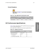
Page 57: ...nna Port guaranteed at 25 C for nonprotected systems See the table below for additional ACU Antenna Coupling Unit loss Table 4 1 Recommended circuit breaker sizes 6 7 8 GHz 10 11 GHz Configuration 24...

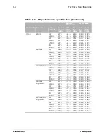
Page 58: ...28 1 76 0 74 5 104 1 102 6 FD 28 5 76 0 74 5 104 5 103 0 FD SD 28 5 76 0 74 5 104 5 103 0 28 DS1 DS3 NP 29 0 76 0 74 5 105 0 103 5 NP SD 29 0 76 0 74 5 105 0 103 5 HSd 28 6 75 0 73 5 103 6 102 1 HS S...

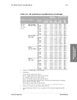
Page 59: ...1 1 72 5 71 0 103 6 102 1 FD 31 5 72 5 71 0 104 0 102 5 FD SD 31 5 72 5 71 0 104 0 102 5 4xDS3 Standard Gain NP 29 0 69 0 68 0 98 0 97 0 NP SD 29 0 69 0 68 0 98 0 97 0 HSd 28 6 68 0 67 0 96 6 95 6 HS...

Page 60: ...6 100 7 99 2 HS SD 26 6 75 0 73 5 101 6 100 1 ST SD 26 6 75 0 73 5 101 6 100 1 FD 27 0 75 0 73 5 102 0 100 5 FD SD 27 0 75 0 73 5 102 0 100 5 16 DS1 High Gain NP 27 0 77 0 76 0 104 0 103 0 NP SD 27 0...

Page 61: ...100 1 FD 30 0 72 0 70 5 102 0 100 5 FD SD 30 0 72 0 70 5 102 0 100 5 4xDS3 Standard Gain NP 27 5 68 5 67 5 96 0 95 0 NP SD 27 5 68 5 67 5 96 0 95 0 HSd 27 1 67 7 66 7 94 8 93 8 HS SD 27 1 68 5 67 5 9...

Page 62: ...4 0 72 5 98 6 97 1 HS SD 24 6 75 0 73 5 99 6 98 1 ST SD 24 6 75 0 73 5 99 6 98 1 FD 25 0 75 0 73 5 100 0 98 5 FD SD 25 0 75 0 73 5 100 0 98 5 16 DS1 High Gain NP 25 5 77 0 76 0 102 5 101 5 NP SD 25 5...

Page 63: ...28 5 68 0 67 0 96 5 95 5 HSd 28 1 67 0 66 0 95 1 94 1 HS SD 28 1 68 0 67 0 96 1 95 1 ST SD 28 1 68 0 67 0 96 1 95 1 FD 28 5 68 0 67 0 96 5 95 5 FD SD 28 5 68 0 67 0 96 5 95 5 a System gain Tx power ou...

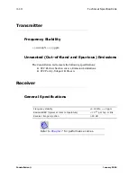
Page 64: ...ns The Constellation radio meets the following specifications FCC Part 101 Section 101 111 Emission Limitations FCC Part 15 Subpart B Class A Receiver General Specifications Refer to Chapter 7 for per...

Page 65: ...for the majority of radios the exceptions are the 16T high gain radio with an acquisition time of 130 ms and the 28 T high gain radio with an acquisition time of 100 ms For RF signal failures lasting...

Page 66: ...Impedance Connector Line Code Length DS1 1 544 100 ohms 50 pin AMI B8ZS 655 feet to DSX 1 E1 2 048 120 ohms 50 pin HDB3 6 dB at 1 024 MHz DS3 44 736 75 ohms BNC female B3ZS 450 feet to DSX 3 E1 waysid...

Page 67: ...yside is disabled the associated overhead bytes are passed through the radio transparently Tributary Bit Rate Mbit s Bellcore ANSI ITU T DS1 1 544 GR 499 CORE Section 9 3 T1 102 1993 G 703 DS3 44 736...

Page 68: ...S1 302 16 DS1 177 16T High Gain 1 5 ms 28 DS1 105 28T High Gain 780 DS3 85 4DS3 180 Capacity Modulation Format Occupied Bandwidth MHz Symbol Rate Msym s Agg Bit Rate Mbit s 8 DS1 32 QAM 3 43 2 74 13 7...

Page 69: ...e path protection is accomplished in less than 60 milliseconds HS Receiver Switching Hot standby Receiver protection switching is automatically caused by a Receiver fault and does not revert to the ma...

Page 70: ...ept for 16T high gain at 130 ms or less and 28 T high gain at 100 ms or less For temporary signal interruptions of 1 to 2 seconds duration no more than 5 of recovery times will exceed 0 5 second Super...

Page 71: ...tors are MAJOR red MINOR red STATUS yellow Site Status Inputs and Control Outputs Eight relay outputs and eight opto isolated alarm inputs are provided on External Alarm Control connector Input level...

Page 72: ...nal Degradation B2 On Line Mod Tx A On Line Mod Tx B On Line Rx A On Line Rx B On Line HLM Manual Control external site control Relay Specifications Radio alarm relays are provided as dry relay contac...

Page 73: ...Subpart B for Class A devices Conducted Emissions ETS 300 826 Bellcore TR TSY 000752 14 5 2 Ambient Temperature Humidity and Altitude Earthquake Shock and Vibration Test specification IEC 721 3 1 Rack...

Page 74: ...fully configured ACU and doors Cannot be flush mounted With ADM 1 3xDS3 and OC3 use back to back terminals Weights Typical Configuration Unit Height Depth Width Terminal Millimeters 622 300 445 Inche...

Page 75: ...CONNECT AND CONFIGURATION C H A P T E R 5 SYSTEM INTERCONNECT AND CONFIGURATION System Interconnection Orderwire Interconnection Table 5 1 describes the interconnection between the Harris MCD Service...

Page 76: ...n female MegaStar VF1B DB 25 female VF2A DB 25 female VF2B MicroStar L 4W VF RJ 45 MicroStar L 16 E1 DE 9 female MicroStar M 1 rms IDU DC 37 female MicroStar M H 3 rms IDU DE 9 female VF PORT 2 RJ45 D...

Page 77: ...nstallation and Maintenance manual for detailed pinout information DATA PORT RJ45 DVSII DATA1 50 pin female RS 232 1 2 DATA2 DATA3 DATA4 MegaStar DATA1 DA 15 female DATA2 MicroStar L M H DATA DE 9 fem...

Page 78: ...fault 7 dBm 0 dBm default 16 dBm Table 5 3 Four wire VF ports performance specificationsa a Specifications are for one drop insert Frequency response 300 3400 Hz 1 5 dB Idle noise C message 30 dBrnc0...

Page 79: ...derwire Interface Connector RJ45 Maximum Distance 50 feet worst case One data channel provides two RS 232 ports Two RS 232 data ports can be selected to be bridged together providing half duplex commu...

Page 80: ...January 2006 5 6 System Interconnect and Configuration Table 5 5 Output voltage range with 7k ohm load Minimum V Maximum V Low 5 11 High 5 11 Table 5 6 Input voltage range Minimum V Maximum V Low 0 0...

Page 81: ...ection Constellation Port Connector Type Radio Equipment Port Connector Type Signal AUX RJ45 Constellation AUX RJ45 RS 422 SPUR SPUR VERSAT1LITY RJ45 CAU COMM 1 DE 9 female RS 232 or RS 423 COMM 2 COM...

Page 82: ...female RS 232 COMM 2 COMM 3 RTU DVA COMM 1 DE 9 female RS 232 COMM 2 GlobeStar RTU DE 9 female RS 232 MegaStar AUX DE 9 female RS 232 SPUR MicroStar L M H RTU DE 9 female RS 232 FSCAN RJ45 FarScan PC...

Page 83: ...9 to 7 125 CMR 137 6 32 7 1 to 8 5 CMR 112 6 32 10 5 to 11 7 UG 39 8 32 Table 6 2 Spacer adapter height standard other interfaces available Band GHz Flange Type Main Spacer Height Space Diversity Spac...

Page 84: ...for availability Table 6 3 Available ACU configurations ACU Configuration NP Tx Rx NP SD Tx Rx Rx HS Tx Rx HS SD Tx Rx Rx HS prot split Tx SD Rx Tx Rx Tx Rx HS 2 antennas Tx Tx Rx Rx FD 1 antenna Tx T...

Page 85: ...ACU hot standby front view 6 5 ACU hot standby Transmitters space diversity Receivers top view 6 5 ACU hot standby Transmitters space diversity Receivers front view 6 6 ACU hot standby frequency dive...

Page 86: ...ellation January 2006 6 4 Antenna Coupling Unit ACU Figure 6 2 ACU nonprotected front view mechanical drawing Figure 6 3 ACU hot standby top view mechanical drawing 1 Refer to Table 6 2 on page 6 1 RX...

Page 87: ...6 5 ANTENNA COUPLING UNIT ACU Figure 6 4 ACU hot standby front view mechanical drawing Figure 6 5 ACU hot standby Transmitters space diversity Receivers top view mechanical drawing 1 Refer to Table 6...

Page 88: ...Unit ACU Figure 6 6 ACU hot standby Transmitters space diversity Receivers front view mechanical drawing Figure 6 7 ACU hot standby frequency diversity 2 antenna T R T R top view mechanical drawing 1...

Page 89: ...on Constellation ACU Configuration and Mechanical Drawings 6 7 ANTENNA COUPLING UNIT ACU Figure 6 8 ACU hot standby frequency diversity 2 antenna T R T R front view mechanical drawing 1 Refer to Table...

Page 90: ...tenna Coupling Unit ACU Figure 6 9 ACU repeater dual terminal mechanical drawing Table 6 4 X dimension from floor ACU repeater dual terminal ACU frequency GHz X dimension inches 6 80 24 7 8 79 61 11 7...

Page 91: ...nfiguration Port 1 Port 2 Port 3 NP Tx Rx TX RX NP SD Tx Rx Rx TX RX RX HS Tx Rx TX RX HS SD Tx Rx Rx TX RX RX HS 2 antennas Tx Tx Rx Rx TX TX RX RX HS FD 2 antennas Tx Rx Tx Rx TX RX TX RX FD 1 anten...

Page 92: ...Constellation January 2006 6 10 Antenna Coupling Unit ACU...

Page 93: ...nterference T I curve 6 GHz and 7 8 GHz 16 DS1 4 Typical threshold to interference T I curve 10 11 GHz 16 DS1 5 Typical threshold to interference T I curve 6 GHz and 7 8 GHz 28 DS1 DS3 6 Typical thres...

Page 94: ...l is then added until the 10 6 BER point is degraded by 1 dB I The measurement is also made with a CW interfering signal which emulates an analog radio FM emission The ratio is the T I The T I curve i...

Page 95: ...Co channel Adjacent Channel Two Times Adjacent Channel T I dB T I dB T I dB 8 DS1 25 12 40 16 DS1 33 4 32 28 DS1 DS3 29 5 38 OC 3 3xDS3 31 14 57 4xDS3 30 1 29 Table 7 2 Like signal T I for 10 11 GHz...

Page 96: ...o interference T I curve 6 GHz and 7 8 GHz 8 DS1 10 9 8 7 6 5 4 3 2 1 0 1 2 3 4 5 6 7 8 9 10 45 40 35 30 25 20 15 10 5 0 5 10 15 20 Radio Capacity Frequency Band 8 DS1 5850 8500 MHz KEY Constellation...

Page 97: ...ypical threshold to interference T I curve 10 11 GHz 8 DS1 10 9 8 7 6 5 4 3 2 1 0 1 2 3 4 5 6 7 8 9 10 45 40 35 30 25 20 15 10 5 0 5 10 15 20 Radio Capacity Frequency Band 8 DS1 10550 11700 MHz KEY Co...

Page 98: ...ference T I curve 6 GHz and 7 8 GHz 16 DS1 10 9 8 7 6 5 4 3 2 1 0 1 2 3 4 5 6 7 8 9 10 35 30 25 20 15 10 5 0 5 10 15 20 25 30 Radio Capacity Frequency Band 16 DS1 5850 8500 MHz KEY Constellation T I d...

Page 99: ...ypical threshold to interference T I curve 10 11 GHz 16 DS1 10 9 8 7 6 5 4 3 2 1 0 1 2 3 4 5 6 7 8 9 10 35 30 25 20 15 10 5 0 5 10 15 20 25 30 Radio Capacity Frequency Band 16 DS1 10550 11700 MHz KEY...

Page 100: ...curve 6 GHz and 7 8 GHz 28 DS1 DS3 20 18 16 14 12 10 8 6 4 2 0 2 4 6 8 10 12 14 16 18 20 50 45 40 35 30 25 20 15 10 5 0 5 10 15 20 25 30 Radio Capacity Frequency Band 28 DS1 5850 8500 MHz KEY Constel...

Page 101: ...threshold to interference T I curve 10 11 GHz 28 DS1 DS3 20 18 16 14 12 10 8 6 4 2 0 2 4 6 8 10 12 14 16 18 20 35 30 25 20 15 10 5 0 5 10 15 20 25 30 Radio Capacity Frequency Band 28 DS1 10700 11700 M...

Page 102: ...Constellation January 2006 7 10 Performance Curves Figure 7 7 Typical threshold to interference T I curve 6 7 8 10 11 GHz 155 Mbit s 128 TCM...

Page 103: ...Harris Corporation Constellation Threshold to Interference T I Ratios 7 11 PERFORMANCE CURVES Figure 7 8 Typical threshold to interference T I curve 6 7 8 10 11 GHz 4DS3...

Page 104: ...e The Receiver C N curve indicates how signal to noise affects the BER Figure 7 9 Typical BER versus C N curve 8 DS1 16 17 18 19 20 21 22 23 24 10 10 10 9 10 8 10 7 10 6 10 5 10 4 10 3 10 2 Radio Capa...

Page 105: ...ics 7 13 PERFORMANCE CURVES Figure 7 10 Typical BER versus C N curve 16 DS1 22 23 24 25 26 27 28 29 30 10 10 10 9 10 8 10 7 10 6 10 5 10 4 10 3 10 2 Radio Capacity Frequency Band 16 DS1 STS 1 5850 117...

Page 106: ...urves Figure 7 11 Typical BER versus C N curve 28 DS1 DS3 20 21 22 23 24 25 26 10 10 10 9 10 8 10 7 10 6 10 5 10 4 10 3 10 2 Radio Capacity Frequency Band 28 DS1 DS3 5850 11700 MHz KEY Constellation B...

Page 107: ...eiver Signal to Noise Characteristics 7 15 PERFORMANCE CURVES Figure 7 12 Typical BER versus C N curve Constellation 155 1 00E 10 1 00E 09 1 00E 08 1 00E 07 1 00E 06 1 00E 05 1 00E 04 1 00E 03 23 23 5...

Page 108: ...10 7 10 8 10 9 10 10 10 11 10 12 BER OUTAGE 5 5 dB FEC Coding Gain STATIC 21 dB 23 dB 29 5 dB 24 dB BER vs C N and C I 128 QAM with Coherent Detection without Forward Error Correction Constellation128...

Page 109: ...oad characteristics The dynamic range of the Receiver is the range from the low RSL to the high RSL at 10 6 BER or other BER 10 3 outage 10 13 error free and so forth Figure 7 14 Typical BER versus RS...

Page 110: ...Constellation January 2006 7 18 Performance Curves...

Page 111: ...onstellation RACK PROFILES A P P E N D I X A RACK PROFILES 19 inch Rack Frame Figure A 1 and Figure A 2 show the Harris standard rack dimensions Figure A 1 EIA 19 inch rack frame and pedestal detail t...

Page 112: ...Constellation January 2006 A 2 Rack Profiles Figure A 2 EIA 19 inch rack frame and pedestal detail Front View Side View...

Page 113: ...alizer ATPC Automatic Transmitter Power Control AUX Auxiliary port B B8ZS Bipolar with Eight Zero Substitution baseband A frequency band occupied by a modulating information signal Bellcore Bell Commu...

Page 114: ...tal Cross connect System DTMF Dual Tone MultiFrequency E EFS Error Free Seconds EIA Electronic Industries Association EMI Electro Magnetic Interference ERP Effective Radiated Power ES Errored Seconds...

Page 115: ...ndardization ITU International Telecommunication Union J JF JackField L LAN Local Area Network LED Light Emitting Diode LNA Low Noise Amplifier LNC Low Noise Converter Loopback Test A test of the coup...

Page 116: ...e portion of the output noise power stemming from thermal noise at the input at standard noise temperature NP NonProtected NRZ NonReturn to Zero coding NTIA National Telecommunications and Information...

Page 117: ...n media or paths are used for transmitting the same information SES Severely Errored Seconds SLVA Successive Log Video Amplifier SNMP Simple Network Management Protocol SNR Signal to Noise Ratio SPU S...

Page 118: ...Constellation January 2006 Glossary 6 V VF Voice Frequency VSB Very Severe Burst W WAN Wide Area Network X XMTR Transmitter...

Page 119: ...s 6 9 specifications 6 1 asynchronous start stop signals 5 5 B battery noise level 4 2 Bellcore 4 12 4 19 BER residual Receiver 4 10 BER versus C N curve 7 12 BER versus RSL dynamic range curve 7 17 b...

Page 120: ...ons 6 1 four wire VF orderwire interface 5 4 four wire VF specifications 5 4 frequency bands 2 1 frequency spacing 1 1 2 1 frequency stability Receiver 4 10 Transmitter 4 10 full duplex 5 5 fuse panel...

Page 121: ...HLM 4 18 Mod Tx 4 18 Rx 4 18 on hook 5 4 on hook telephone set 5 4 opto isolated alarm inputs 4 17 overload Receiver 4 11 P paired frequencies 2 4 parity option enabled 5 5 performance curves 7 1 jitt...

Page 122: ...s inputs 4 17 SNMP 3 4 4 16 software reverse path protection 4 15 source timing mode for HLM 3 12 space diversity Receiver switching 4 15 spacer adapter height 6 1 specification compliance tributary 4...

Page 123: ...0 unwanted emissions 4 10 Tributary Interface technical specifications 4 12 tributary jitter 4 12 tributary signal characteristics 4 12 tributary specification compliance 4 13 two wire VF orderwire in...

Page 124: ...Constellation January 2006 Index 6...

Page 125: ......

Page 126: ...6 0LFURZDYH RPPXQLFDWLRQV LYLVLRQ DYLV ULYH 0RUULVYLOOH 1 86 ZZZ KDUULV FRP 86 DQDGD RUOGZLGH...

Reviews: