MM-015371-001, Rev. C
28
5
PLANNING THE INSTALLATION
5.1 GENERAL INFORMATION
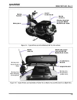
Figure 5-1 on page 29 illustrates a typical M5300/M7300 mobile radio motorcycle installation. Before
starting, plan the installation carefully so it will:
Be safe for the motorcycle operator;
Allow convenient access by the operator, as applicable (i.e., the control head);
Neat; and,
Allow easy service access.
CAUTION
A professional radio installer should perform the installation!
Mounting of the mobile radio components in ways other than those described in
this manual may adversely affect performance, violate FCC rules on RF exposure,
and even damage the unit(s), posing a potential safety hazard.
5.2 RECOMMENDED TOOLS
The following tools are recommended to complete the installation. Where specific vendor names and
model or part numbers are presented, equivalent substitutes may be used:
Non-Insulated Crimp Tool with Wire Cutter
similar to Thomas & Betts WT-111-M
Insulated Terminal Crimp Tool with Wire
Cutter similar to Klein 1005
Fuse Holder Crimp Tool similar to Thomas
& Betts – WT-112M or California Terminal
Products No. 1250 or Channelock No. 909
Ratcheting Hex-Crimp Tool for 50-Ohm
TNC and BNC RF Connectors and RG-58
Cable similar to Tyco Electronics 58433-2
(includes Crimper 354940-1 and Die Set
58436-1) or Cambridge 24-9960P
Metric and S.A.E. Socket Set with Sockets
to at least ½-Inch, a Nut Driver and an
Extension at least 3-Inches Long
Soft-Jaw Pliers similar to Tessco 450520 or
equivalent
Torx Screwdrivers, T10 and T20
Phillips-Head Screwdrivers, #1 and #2
Flat-Blade Screwdrivers, #1 and #2
4-Millimeter Hex Key Wrench
⅛
-Inch Hex Key Wrench (Allen Wrench)
Cordless Electric Drill(s) with Bits
Deburring Tool (for
⅜
-inch and smaller
holes)
Tie Wraps: 6-inches or larger
Flush-Cut and Large Wire Cutters
Various Fasteners (e.g., machine screws and
nuts, Tek screws, etc.)
A separate list of test equipment is included in Section 15.2 on page 70.

