MM-015371-001, Rev. C
44
6.
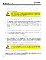
Verify the mounting bracket is held firmly mounted. Firm mounting prevents unreasonable vibration,
which could damage the control head and/or cause its cable connections to loosen.
7.
Slide the control head into the bracket, placing the two pegs protruding from its left and right sides
into the respective round holes in the bracket’s two side “ears.”
8.
In each side “ear” of the mounting bracket, start a #8-32 hex-socket-head cap (Allen) head screw with
a lockwasher and a flat washer by inserting the screw through the slotted hole in the bracket and then
into the threaded hole in the side of the control head. This hardware is included with Mounting
Bracket Kit. The lockwasher should be adjacent to the screw head and the flat washer should be
adjacent to the bracket. Turn each screw clockwise as observed from the head of the screw.
9.
The control head can be positioned at various angles for best display viewing at the normal position
of the motorcycle operator. As necessary, turn it on the pegs to a good position and tighten both
screws using an
⅛
-inch hex key (Allen) wrench until the control head is held firmly in place. Do not
over-tighten.
8.2.3.2
Using the Mounting Pedestal (Optional)
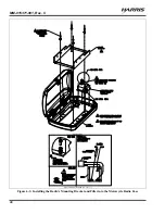
An optional Mounting Pedestal, part number MACDOS0012, may be purchased separately to replace the
standard U-shaped mounting bracket. This pedestal can be attached to the bottom of the control head as
shown in Figure 8-5, and then mounted to a mounting surface below the two. It can also be attached to the
top of the head and then mounted to a mounting surface above the two.

