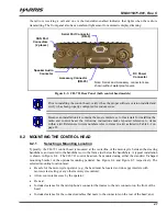
MM-015371-001, Rev. C
48
structural part of the motorcycle’s frame, which could weaken the frame and cause it to crack. If
possible, use an existing hole to ground the black wire.
If an existing hole cannot be located, locate a non-structural metal area of the motorcycle that has a
solid and stable ground connection to the motorcycle’s frame. Drill a
⅜
-inch hole in this metal area,
deburr it, and strip this area of all paint and dirt to expose a bare metal surface, approximately ¾-inch
square. A
⅜
-inch-stud non-insulated ring terminal is supplied with the cable to make this ground
connection. Hole diameter must be appropriate for the utilized grounding screw/bolt size and type
used to connect the ring terminal to the bare metal surface. This hardware is not supplied.
Never comprise the strength of a motorcycle’s frame, handlebars, or other key
components by drilling or grinding holes in these components. Use clamps or
another method approved by the motorcycle manufacturer to attach radio
components.
8.
Cut the excess-length black wire to the required length then strip insulation back approximately
¼-inch.
9.
Crimp a
⅜
-inch non-insulated ring terminal (supplied with the cable) to the end of the black wire,
crimp-on another terminal appropriate for the type of connection hardware being used.
10.
Attach the ring terminal and black wire to the bare metal surface using stainless-steel self-locking
hardware (i.e., machine screws with washers and locking nuts) or other appropriate hardware to
ensure a reliable terminal-to-metal contact. Tighten securely.
11.
Apply an approved paint or rust-inhibitor over the remaining exposed bare metal surface and around
the ring terminal.
10.1.3.2 Red Wire and Main Fuse Holder Connection (Radio’s Main Power Wire)
1.
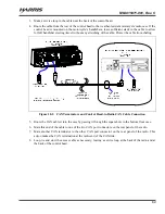
Route the cable’s red wire from the connector at the rear of the radio to the Alternator Whine Reject
Filter near the square hole in the bottom floor of the radio case. Leaving a service loop/slack at the
rear of the radio, cut this wire to a length long enough to reach the DC output stud (stud labeled
“RADIO +”) on the filter. Save the excess-length red wire to make the battery connection.
2.
Strip approximately ¼-inch of insulation from both the end of the red wire from the cable connector
and one end of the excess-length red wire, then crimp a #8-stud ring terminal (has yellow insulation)
to each stripped wire end. These ring terminals are included with the installation kit.
3.
Remove the nut from filter’s DC output stud (stud labeled “RADIO +”) and attach both ring terminals
to this stud. Reinstall the nut. It is not necessary to tighten the nut at this time, since a control head
power wire will be added to this stud in a later procedure.
4.
Route the excess-length red wire out of the square hole in the bottom floor of the radio case.
5.
Route the excess-length red wire to the location of the vehicle’s battery (or its main DC bus bar or
stud). Protect the wire from possible chafing where necessary. Tie and stow the wire as necessary.
CAUTION
Do
not
install any wiring or fuse holders over or in the near vicinity of the motorcycle’s
engine, or near other hot items such as exhaust pipes and mufflers. Excessive heat can
cause permanent damage to these components.

