MM-015371-001, Rev. C
59
12 MICROPHONE ATTACHMENT
There are several versions of microphones available for use with the radio. Each has a 17-pin flush-mount
type connector that mates with the mic connector on the front panel of the control head. The mic’s
connector includes a captive thumbscrew that secures it to the mic connector on the front panel of the
control head. A microphone clip is included with each microphone. The radio can be configured to
provide a monitor function when the microphone is cradled in the clip. Connect the mic to the control
head and install the clip as follows:
1.
Select a mounting surface location that has clearance for the mic when it is stowed in the clip, and
then attach the microphone clip to the surface. The use of self-locking hardware (i.e., machine screws
with washers and self-locking nuts) is recommended. Tighten securely.
2.
Using the microphone clip as a template, drill mounting holes in the surface of the selected location.
3.
The microphone clip must be grounded to the vehicle’s chassis. If not mounted to a grounded metal
surface, complete this requirement by adding a jumper wire attached from chassis ground to the clip.
4.
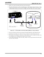
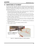
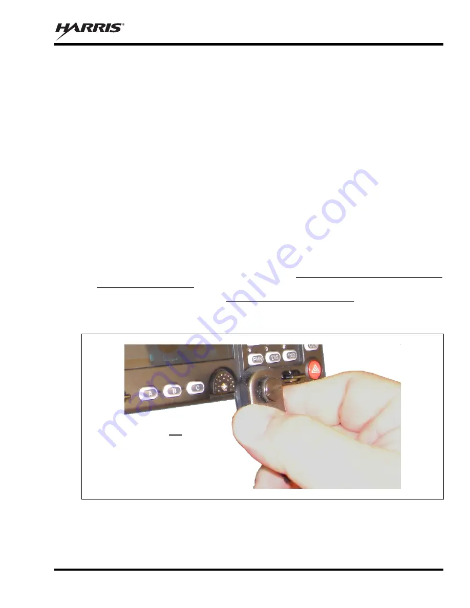
As illustrated in Figure 12-1, grasp the mic’s connector with a thumb and index finger on the sides of
the connector just adjacent to the thumbscrew.
5.
Position connector just in front of the control head’s mic connector so its male pins can engage
straight into the female (socket) pins of the control head’s mic connector. The thumbscrew must be
oriented directly above the hanging mic cable.
6.
Mate the two connectors by pressing them fully together. Do
not
apply any force to the thumbscrew
when mating the connectors.
7.
Tighten the thumbscrew finger-tight. Do
not
use a screwdriver to
tighten
it.
8.
Clip the microphone to the clip.
Figure 12-1: Attaching the Microphone to the CH-721Control Head
As illustrated, do
not
apply any
force to the thumbscrew when
mating the mic connectors.

