MM-015371-001, Rev. C
34
shaped holes in the corners of the Case/Antenna Bracket. The bracket’s triangle-shaped antenna
mounting surface must face to the rear of the motorcycle.
4.
Open-up the case to expose the interior floor in its bottom-half.
5.
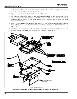
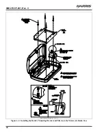
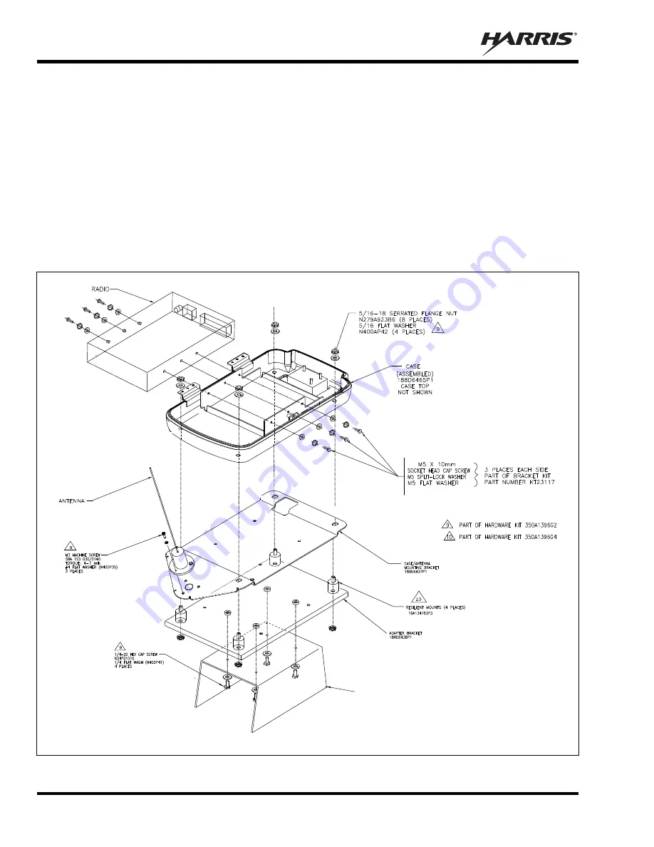
As illustrated in Figure 6-1, place the case over the Case/Antenna Bracket, and onto the
5
/
16
-inch
studs, passing the studs through the holes in the floor of the case. The square hole in the bottom floor
of the case must be towards the front of the motorcycle, so it is directly over the square hole in the
Case/Antenna Bracket.
6.
Place a
5
/
16
-inch stainless-steel flatwasher onto each of the four
5
/
16
-inch studs protruding through the
holes in the floor of the case. These flatwashers are included in Hardware Kit 350A1396G2 (Item 6 in
Table 4-2).
7.
Add four
5
/
16
-inch serrated nuts to the studs (each nut’s washer side down), and tighten all four nuts
securely. A torque of approximately 100 in.-lbs. (11.3 N.m.) is recommended.
MOTORCYCLE’S RADIO BRACKET
(NOT SUPPLIED)
(Made From AA01-MAMV, Sh. 2, Rev. -)
Figure 6-1: Assembling, Mounting and Installing the Radio Case and Brackets

