MM-015371-001, Rev. C
41
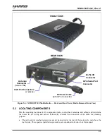
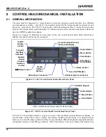
the radio is receiving a call and one is the transmitter-enabled indicator that lights when the radio is
transmitting. The front panel also has an ambient light sensor for automatic display dimming.
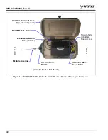
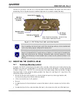
Figure 8-3: CH-721 Rear Panel (both control head models)
Prior to installing the control head, verify it has the proper software version installed and
verify it has been properly configured for customer use.
Because an installation kit contains the most complete set of materials for installing the
radio and control head, the following instructions make repeated reference to items
within a kit. References to item numbers refer to items in a kit as listed in Table 4-2 on
page 22.
8.2 MOUNTING THE CONTROL HEAD
8.2.1
Selecting a Mounting Location
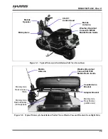
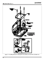
Typically, the CH-721 control head is mounted at the centerline of the motorcycle between the steering
handlebars, and secured to the handlebars or to the frame just below the handlebars. A typical installation
is shown in Figure 8-4. The CH-721 control head can be mounted using either the standard U-shaped
mounting bracket or the optional mounting pedestal. See Figure 8-4 and Figure 8-5 respectively. The
selected mounting location must:
Be safe for the motorcycle operator (e.g., the head must be located so it does not interfere with
motorcycle steering or any other motorcycle controls);
Allow convenient access by the operator;
Be neat;
Include clearance for the microphone’s connector that mates to the mic connector on the front of the
head;
Include clearance for the connectors/cables that mate to the connectors on the rear of the head; and,
CAN Port
Connectors
(2 places)
Speaker Audio
Connector
Serial Port Connector
(DB-9)
DC Power
Connector
Accessory Connector
(DB-25)
Note: Serial and Accessory connectors are
shown without waterproof covers.

