MM-015371-001, Rev. C
52
4.
Using an appropriate electrical terminal, connect this short white wire to unswitched 12-volt DC
power source at or near the vehicle’s fuse box.
5.
Cut another section of white wire from the cable. This wire must be long enough to reach from this
fuse holder to the location of the panel-mounted on/off switch.
6.
Strip one end of this wire and crimp the other half of the waterproof fuse holder to this wire end.
7.
Strip the other end of this wire and, using an appropriate electrical terminal, connect it to the common
terminal of the switch.
8.
Connect the white wire of the power cable to the load (switched) side of the switch.
9.
If not already, mount the switch to the motorcycle’s instrument panel, or other customer-selected
location.
10.
Obtain the 3-amp AGC-type fuse included with the cable, and install it into the fuse holder.
11.
Tie and stow these wires as necessary so they remain out of the way of casual contact and wire chafe
is avoided.
12.
Label this power switch accordingly. For example: “
RADIO ON/OFF
.”
10.1.4.2.3
Control Head and Radio Are “Hot Wired”
In the “hot-wired” configuration, the control head and radio are turned on and off only by the control
head’s on/off/volume control located on the front panel of the control head. In this configuration, the
control head’s white wire must be connected to
unswitched and fused 12-volt
vehicle power. Follow the
procedure presented in Section 10.1.4.2.1, except connect the white wire to
unswitched
battery power
instead of switched (“Accessory”) power.
10.2 CAN CABLE CONNECTIONS
10.2.1
General Information
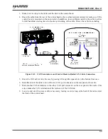
As illustrated in Figure 10-1, the radio installation requires a Controller Area Network (CAN) cable
between the radio and the control head, a CAN terminator at the radio, and a CAN terminator at the
control head. The radio and the control head each have two (2) CAN port connectors on the rear panel.
10.2.2
Make CAN Link Terminations and Cable Connection
Follow this procedure to make the CAN line interconnections:
1.
Mate a CAN terminator (item 14 in Table 4-2) onto either one of the two smaller 3-pin CAN port
connectors on the rear panel of the CH-721. This action makes the CAN termination at the control
head end of the CAN link.
When mating any CAN connection (terminators and cables) to a rear panel connector,
visually align the ¾-moon-shaped keys of the connectors, and then gently push and
turn the outer locking ring of the plug (male) connector clockwise until it stops. A mild
click will be sensed to confirm proper mating. Without visual alignment as a guide, it
is possible with excessive force to mate the CAN connectors improperly. Damage to
the connector(s) may result. Therefore, visual alignment is recommended when mating
CAN connectors.
2.
Obtain a CAN cable and mate it to the other CAN port connector on the rear panel of the CH-721.
Typically, item 13 in Table 4-2 is utilized, a 30-foot CAN cable.


