background image

NEXIO AMP

Hardware Installation and User Guide

23

©2011 Harris Corporation. All rights reserved.

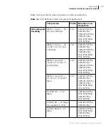
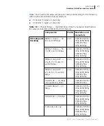
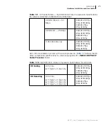
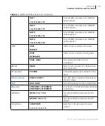
Table 1-8

shows the HD video compression coding and decoding for the following

when connected via Media Host architecture:

3 Channel (0  3 play only)

3 Channel (1  2 play only)

Table 1-8

3 Channel Mode — High Definition Video Compression Specifications

(for servers connected via Media Host Architecture)

Compression

Profile Resolution and

Frame Rate

HD Coding and
Decoding

MPEG-2 l-frame — 50,
80, and 100 Mbps

4:2:0

1080i @ 29.97fps
720p @ 59.94fps
1080i @ 25fps
720p @ 50fps

MPEG-2 l-frame — 50,
70, 80, and 100 Mbps

4:2:2

1080i @ 29.97fps
720p @ 59.94fps
1080i @ 25fps
720p @ 50fps

MPEG-2 Long GOP —
18, 25, 35, 50, 60, 70,
and 80 Mbps

4:2:0

1080i @ 29.97fps
720p @ 59.94fps
1080i @ 25fps
720p @ 50fps

MPEG-2 Long GOP —
25, 35, 50, 70, and 80
Mbps

4:2:2

1080i @ 29.97fps
720p @ 59.94fps
1080i @ 25fps
720p @ 50fps

XDCAM HD — 35 Mbps
(not available in 720p)

1080i @ 29.97fps
1080i @ 25fps

XDCAM HD422 — 50
Mbps

1080i @ 29.97fps
720p @ 59.94fps
1080i @ 25fps
720p @ 50fps

XDCAM EX — 35 Mbps

1080i @ 29.97fps
720p @ 59.94fps
1080i @ 25fps
720p @ 50fps

H.264 (decode only)

1080i @ 29.97fps
720p @ 59.94fps
1080i @ 25fps
720p @ 50fps

Summary of Contents for NEXIO AMP NX3801HDX

Page 1: ...459 3400 www broadcast harris com 2007 Harris Corporation Part Number 175 000407 00 Harris is a registered trademark of Harris Corporation Trademarks and tradenames are the property of their respectiv...

Page 2: ......

Page 3: ...April 2011 NEXIO AMP NX3801HDX Shared Storage Server Hardware Installation and User Guide 175 100244 00 REV A...

Page 4: ...n DFAR 252 227 7015 Nov 1995 or FAR 52 227 14 June 1987 whichever is applicable You agree not to remove or deface any portion of any legend provided on any licensed program or documentation contained...

Page 5: ...Harris Product 5 Chapter 1 Introduction 9 System 15 Video 15 Audio 17 Video Compression 17 Storage 26 RAID Redundancy 26 Timecode Connection Options 26 Remote GPI Control 27 Remote Serial Interface 2...

Page 6: ...ections 57 Testing Input and Output Signals 57 Chapter 4 Using NEXIO Config 61 Creating or Modifying a Preset 64 Creating a Default Preset 65 Information 69 Channel Configuration 70 Video Options 71 A...

Page 7: ...Guide v 2011 Harris Corporation All rights reserved Testing the LED Lights 106 Selecting Monitored Diagnostics 106 Checking Status 107 LCD Keypad Buttons 109 Chapter 6 Connectors Jumper Settings and C...

Page 8: ...Contents vi 2011 Harris Corporation All rights reserved...

Page 9: ...tarted 47 To start NEXIO AMP 47 To log on to NXOS 49 To create the deployment dc file 52 To confirm connection to additional systems 56 To test I O signals on a channel 57 To test output signals on re...

Page 10: ...LM registry settings 89 To change MPEG registry settings 91 To change FTP parameters 93 To change Startup registry settings 95 To change CV Logo registry settings 97 To change Other registry settings...

Page 11: ...gives you important information on unpacking and shipping your Harris product This guide introduces and describes procedures for installing and using NEXIO AMP If the information in the release notes...

Page 12: ...bout connecting NEXIO AMP Chapter 2 Hardware Installation on page 29 Start up information for NEXIO AMP Chapter 3 Getting Started on page 47 Configuring video and audio settings for NEXIO AMP Chapter...

Page 13: ...field Indicates the direction of navigation through a hierarchy of menus and windows hyperlink Indicates a jump to another location within the electronic document or elsewhere Internet address Indicat...

Page 14: ...r Guide Software License Key Registration Card NEXIO Server Protocol Developer Guide Obtaining Documentation Manuals User Guides and other documents can be viewed or downloaded from the Harris website...

Page 15: ...e occurred during transit 2 Confirm that you have received all items listed on the packing list 3 Contact your Harris NEXIO dealer if any item on the packing list is missing 4 Contact the carrier if a...

Page 16: ...t to you by prepaid ground shipping after servicing Technical Support Technical support is available 24 hours a day 7 days a week You can contact technical support by phone or e mail Harris Broadcast...

Page 17: ...ail Infrastructure products Service europe harris com RMA s RMArequest europe harris com DAM Support HClassDAMsupport emea Harris com ADC Automation HasHelp Harris com D Series Support DALSupport Harr...

Page 18: ...About This Guide 8 2011 Harris Corporation All rights reserved...

Page 19: ...d access to NEXIO s shared storage system via NEXIO s RAIDsoft software RAID controller NEXIO AMP is software configurable and uses software codec technology to encode and decode HD and SD content NEX...

Page 20: ...details on licensing your software see Registering Your Software on page 51 or the Software License Card provided with your server SD only channel configurations do not support up down cross conversio...

Page 21: ...des hardware assisted codec support for up to 4 channels of AVC Intra play out 50 and 100 Mbps or 2 channels of AVC Intra encoding To determine if your system meets the requirements needed for NEXIO A...

Page 22: ...Navigator Monitors and provides system wide diagnostics for NEXIO servers and associated system components NEXIO ClipSync Play back two separate clips together at the same time frame accurately NEXIO...

Page 23: ...Media Host architecture Supports NEXIO Farad shared storage Software based codecs for coding and decoding SD and HD media Supports up to 8 SD channels or up to 4 HD channels Supports SD 525i 625i and...

Page 24: ...C EIA 608 EIA 708 and WST OP 47 closed caption transcoding using software based real time processing HD licensed servers only Easy integration with IP networks using Gigabit Ethernet for media transfe...

Page 25: ...Two Six Core AMD Opteron 64 bit processors PCI Express platform 16 GB RAM Dual mirrored boot drives Two redundant 8 Gb Fibre Channel ports Four 10 100 1000Base T Ethernet adapters Dual head DVI I mon...

Page 26: ...0i 25fps 1080p 29 97fps 1080p 25fps 720p 59 94fps 720p 50fps SD Input Output Configurations See Table 1 1 on page 10 HD Input Output Configurations See Table 1 1 on page 10 SD Aspect Ratio 4 3 16 9 HD...

Page 27: ...mination 1V p p nominal levels Processing Storage 16 20 or 24 bit PCM 48kHz Compressed Audio Dolby Digital AC 3 and Dolby E pass through Table 1 5 Standard Definition Video Compression Specifications...

Page 28: ...y SLK Table 1 5 shows the SD video compression coding and decoding DVCPRO25 is the same as DVCAM in 525 29 97fps Table 1 5 Standard Definition Video Compression Specifications Compression Profile Reso...

Page 29: ...fps MPEG 2 l frame 50 70 80 100 120 and 150 Mbps 4 2 2 1080i 29 97fps 1080i 25fps 1080p 29 97fps 1080p 25fps 720p 59 94fps 720p 50fps MPEG 2 Long GOP 18 25 35 50 60 70 and 80 Mbps 4 2 0 1080i 29 97fps...

Page 30: ...only 2 Channel 2 bi directional 0 play only XDCAM EX 35 Mbps 1080i 29 97fps 720p 59 94fps 1080i 25fps 720p 50fps H 264 decode only 1080i 29 97fps 720p 59 94fps 1080i 25fps 720p 50fps DNxHD 1080i 29 9...

Page 31: ...5fps 1080p 29 97fps 1080p 25fps 720p 59 94fps 720p 50fps MPEG 2 l frame 50 70 80 100 120 and 150 Mbps 4 2 2 1080i 29 97fps 1080i 25fps 1080p 29 97fps 1080p 25fps 720p 59 94fps 720p 50fps MPEG 2 Long G...

Page 32: ...720p 50fps XDCAM EX 35 Mbps 1080i 29 97fps 720p 59 94fps 1080i 25fps 720p 50fps H 264 decode only 1080i 29 97fps 720p 59 94fps 1080i 25fps 720p 50fps DNxHD 1080i 29 97fps 720p 59 94fps 1080i 25fps 720...

Page 33: ...ng MPEG 2 l frame 50 80 and 100 Mbps 4 2 0 1080i 29 97fps 720p 59 94fps 1080i 25fps 720p 50fps MPEG 2 l frame 50 70 80 and 100 Mbps 4 2 2 1080i 29 97fps 720p 59 94fps 1080i 25fps 720p 50fps MPEG 2 Lon...

Page 34: ...ions for servers connected via Media Host architecture Compression Profile Resolution and Frame Rate HD Coding and Decoding MPEG 2 l frame 50 Mbps 4 2 0 1080i 29 97fps 720p 59 94fps 1080i 25fps 720p 5...

Page 35: ...35 Mbps 1080i 29 97fps 720p 59 94fps 1080i 25fps 720p 50fps H 264 decode only 1080i 29 97fps 720p 59 94fps 1080i 25fps 720p 50fps Table 1 10 High Definition Video Compression Specification for AVC Int...

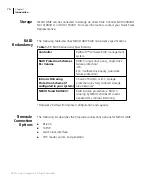
Page 36: ...bes the timecode connections options for NEXIO AMP RS 232 TCP IP Leitch clock interface VITC reader writer and generator Table 1 11 RAID Redundancy Specifications Controller RAIDsoft software RAID man...

Page 37: ...ut see NEXIO AMP RS 422 Pinouts on page 115 Controls The following table describes NEXIO AMP control specifications Physical The following table describes NEXIO AMP size specifications Table 1 12 GPI...

Page 38: ...undant dual hot swappable dual load sharing AC 115 120 V 200 240 V auto select 60 50 Hz 750 W Supported Television Formats NEXIO AMP supports the following television standard formats 525 29 97fps 625...

Page 39: ...g and support equipment Power source Connect the power inlet to an adequate power source Using a UPS is strongly recommended Connect each of the two redundant power supply connections to a separate el...

Page 40: ...chassis The release latch on the slide faces the rear of the frame 3 Attach an extension to the back of each rail to match the depth of your rack 4 Attach the rails to the rack posts 5 Pull the inner...

Page 41: ...y For more information on rack mounting see the NEXIO NX3801HDX Installation Quick Start Guide Connecting NEXIO AMP This section contains the following topics Rear Panel Port Connectors on page 31 Rea...

Page 42: ...EF IN input If the loop through is not used connect a 75 terminator to this jack LOOP IN1 LOOP IN2 LOOP IN3 LOOP IN4 Four BNC connectors for loop through of inputs 1 through 4 OUT1 OUT2 OUT3 OUT4 Four...

Page 43: ...KEYBOARD USB3 USB4 Two unassigned USB 2 0 port connectors RS232 RS232 9 pin D sub connector for RS232 serial port connection PC Speaker PC SPKR Computer speaker port connector Not used Fibre Channel P...

Page 44: ...y alarm reset button silences the power supply alarm Power Supplies NEXIO AMP has two redundant hot swappable power supplies located on the back panel Under normal operation both power supplies work i...

Page 45: ...sync reference connection A valid reference signal must be applied to the REF IN port when the system is configured for external sync Looping is not recommended If you do loop use caution when loopin...

Page 46: ...for HD SDI with the NEXIO AMP frame for example the Belden 1694A cable Cable used for analog SDI and ASI devices may not be high enough quality AES Audio The audio ports use HD BNC connectors for AES...

Page 47: ...NXUSBTC User Guide and your Adrienne AEC Box NXUSBTC documentation PC Speaker Computer speaker port connector Not used Fibre Channel Orange fiber optical cables provided are used to connect the frame...

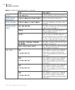
Page 48: ...ration and Category 5e or 6 cables are required for operation at 1000 Mbps NEXIO AMP The default Ethernet port allocations for NEXIO AMP are shown in Table 2 2 1 Gigabit Ethernet is required The possi...

Page 49: ...are using a Media Host architecture 1 In NEXIO Config click the IP Config tab see page 82 2 In the Role list select Not Assigned for all Ethernet connections 3 In the Hi Res Net Server MIOH area ente...

Page 50: ...cal infrastructures must be supported by separate switches or switch infrastructures The two physical infrastructures must be of the same caliber hardware For example do not use a 1000BASE T infrastru...

Page 51: ...a Media Host architecture 1 In NEXIO Config click the IP Config tab see page 82 2 In the Role list select Not Assigned for all Ethernet connections 3 In the Hi Res Net Server MIOH area enter the IP a...

Page 52: ...any Ethernet port Ethernet ports 3 and 4 can be teamed for port redundancy Do not team Ethernet ports 3 and 4 if they are used in servers with the low resolution proxy PRXEncoder application If Media...

Page 53: ...are codec based therefore codec 0 channel 1 etc For more information on configuring COM ports see NEXIO AMP RS 422 Pinouts on page 115 Table 2 4 Default COM Port Channel Configurations Mode COM Port C...

Page 54: ...ribed below LED Indicators LCD LCD Keypad Boot Drives USB Ports FireWire Port SYS ID Indicator Figure 2 4 NEXIO AMP Front Panel LED Indicators The LED indicators are on the front of NEXIO AMP The LED...

Page 55: ...ton The power on reset button enables you to turn on NEXIO AMP and reset the system as described below Turn On press and hold the button for 5 seconds to power on the system System Reset when powered...

Page 56: ...3 USB Ports The front of NEXIO AMP has two USB 2 0 ports For more information see USB on page 36 Firewire Port NEXIO AMP has an IEEE1394 Firewire port connector that can be used for a portable storage...

Page 57: ...how to start the NEXIO AMP and the initial startup tasks that you should perform After you have performed the tasks described here you should run the Using NEXIO Config on page 61 to assign your vide...

Page 58: ...for starting these applications Starts the Low Level Module LLM The LLM application is the core software component for communication and video audio I O in your NEXIO system Starts the FTP Server The...

Page 59: ...reserved To log on to NXOS 1 In the Accounts list click Administrator The Administrator user name appears in the User Name box see Figure 3 1 2 In the Password box type system This is the default pas...

Page 60: ...ing Started 50 2011 Harris Corporation All rights reserved The NXOS main window appears see Figure 3 2 Your MediaBase clip list will be empty if no clips are stored on the server system Figure 3 2 NXO...

Page 61: ...your software does not get registered during the commissioning process you can register your software To register your software you will need to send Harris BCD Support the deployment file dc file for...

Page 62: ...m Files x86 Harris SLK folder Figure 3 3 SLK Folder 2 Double click RM exe to open the Registration Manager Tip You can also click Start Programs Harris Software License Key Registration Manager to ope...

Page 63: ...ation All rights reserved The Software License Key Registration Manager appears Figure 3 4 Software License Key Registration Manager Tip You can click an application and then click Features configurat...

Page 64: ...ame and the serial number found on the right hand side of the server Make sure to scan your USB stick before inserting it into the computer and again before inserting it into the server to prevent vir...

Page 65: ...e USB stick and insert it into server 9 Open the Software License Key Registration Manager as described above 10 In the Open dialog box locate the USB stick and double click the rc file 11 Run the app...

Page 66: ...s area Figure 3 8 LLM Main Window To confirm connection to additional systems 1 In the Nodes pane confirm that the video server that you are currently logged on to and any other active nodes are displ...

Page 67: ...cables Confirm that all audio and video I O cables are connected properly and securely Testing Input and Output Signals Test signals on all connected channels You can verify input and output signals...

Page 68: ...o 2 minutes is recommended 4 Click OK The new ID name appears in the ID box in the channel window and in the MediaBase window The Record button see Figure 3 11 is available indicating that the clip is...

Page 69: ...into a play only window 7 Confirm successful playback on a connected monitor 8 If the video server has a second ingest channel repeat the procedure above for Channel 2 ingest To test output signals on...

Page 70: ...clip from an ingest channel window to a playout channel window For example drag a clip from Channel 1 and drop it in Channel 3 You may do this while recording a clip in Channel 1 Press the Play button...

Page 71: ...ast reliable setup of multiple servers In this chapter you will learn how to work with configuration presets You will also be provided detailed information on each NEXIO Config window This chapter inc...

Page 72: ...XIO Config Double click on the NEXIO Config desktop shortcut see Figure 4 1 Figure 4 1 NEXIO Config Desktop Shortcut The NEXIO Config Information window appears see Figure 4 2 Figure 4 2 NEXIO Config...

Page 73: ...ring Your Software on page 51 Working with Configuration Presets NEXIO Config allows you to select an existing preset or create a new preset to use for your configuration You can easily apply and disc...

Page 74: ...t the desired preset or select new to create a new preset 2 Make the desired changes to each NEXIO Config window You can click Discard at anytime to discard all the changes made to the selected config...

Page 75: ...cify a selected configuration as the default preset To restore the factory default settings 1 Click the Defaults icon The Defaults dialog box appears see Figure 4 4 Figure 4 4 NEXIO Config Factory Def...

Page 76: ...ory defaults To specify a default preset 1 Create a preset as described in Creating or Modifying a Preset on page 64 2 In Windows Explorer open the presets folder Tip The presets folder is in C Progra...

Page 77: ...Default Preset Message 7 Click Yes to open the Apply Changes dialog box and review the changes prior to restoring the default preset OR Click No to restore the default preset without reviewing the ch...

Page 78: ...s on page 78 Automation Serial on page 79 IP Config on page 82 FTP Folders on page 85 LLM Parameters on page 86 Error Logging on page 87 LLM on page 89 MPEG on page 91 FTP on page 93 Startup on page 9...

Page 79: ...O domain to which this server belongs and its node number in that domain Hardware indicates the number and type of processors and the amount of RAM in the server Platform identifies the NEXIO server p...

Page 80: ...rdware Figure 4 12 NEXIO Config Channel Configuration If a value appears in a box that is grayed out the value is valid but cannot be edited In addition if a check box is selected and is grayed out th...

Page 81: ...check boxes for the options that you want to include and clear the check boxes for the options that you want to exclude Video Options The NEXIO Config Video Options window Figure 4 13 allows you to sp...

Page 82: ...s the recommended setting The available Resolution settings are Standard use for bi level 525 or 625 line reference HD1080i use for tri level 1080i reference HD720 use for tri level 720p reference HD1...

Page 83: ...9 option and then select the desired ARC setting The selected ARC setting becomes the default ARC setting for any SD 4 3 clips that do not have pre defined ARC settings loaded into that channel The av...

Page 84: ...RC setting from the list The selected ARC setting becomes the default ARC setting for any SD 4 3 clips that do not have pre defined ARC settings loaded into that channel The available settings for an...

Page 85: ...output will appear on line 18 This option is only applicable for SD only clips and if VITC insert is selected e Select the Legacy timecode display check box to report a channel s current output timeco...

Page 86: ...ar different than the actual hardware Figure 4 14 NEXIO Config Audio Options To specify audio options 1 Click All Channels to set the audio configuration for all of the channels or click the desired c...

Page 87: ...when AES EBU is Selected 3 In the Audio Bits area click the number of bits per sample i e 16 Bit 20 Bit or 24 Bit 4 In the Audio Tracks area select the number of audio tracks i e 4 8 or 16 5 In the Au...

Page 88: ...djust the volume GPRX Options The GPRX Options window Figure 4 14 allows you to select the video and audio bit rates for GPRX low resolution proxy Figure 4 16 NEXIO Config GPRX Options To specify GPRX...

Page 89: ...u to set control ports general parameters and VDCP parameters for your configuration Figure 4 17 NEXIO Config Automation Serial To specify each available 422 port 1 In the Channel VTR list select the...

Page 90: ...xact Duration Update list select one of the following 0 to disable exact duration update 1 to guarantee that playback from any node of the system will not overrun the media written to disk 4 In the Jo...

Page 91: ...k box to enable jog smooth If the jump threshold is exceeded then VDCP Jog command performs a jump without a scrub otherwise it performs a smooth jog with scrub In the Jump Threshold list select one o...

Page 92: ...rved IP Config The NEXIO Config IP Config window Figure 4 18 allows you to specify the following network settings Server and Order Configuration Network Settings LLM Domain and Node Settings High Res...

Page 93: ...o by Harris BCD Support 3 In the Platform Type list change the default platform type only if instructed to do so by Harris BCD Support The Platform Type is read by the registry and should match the Pl...

Page 94: ...Number greater than 127 or the LLM will not launch 6 If the computer is connected to the NEXIO Storage SAN through a network server Media Host architecture in the High Res Network Server MIOH area ty...

Page 95: ...XIO Config FTP Folders To change virtual folders settings 1 In the Virtual Folders area select the file types for which you want to create virtual folders Tip Virtual folders are used to identify whic...

Page 96: ...rver parameters Do not change these settings unless you are instructed to do so by Harris BCD Support Figure 4 23 NEXIO Config LLM Parameters To change LLM parameters 1 In the Raid Configuration area...

Page 97: ...Debug Codes area The number of days a log is kept and the size of the log options apply to the errlog txt tract txt traceVDCP txt and rwerrlog txt These logs are located in the C VR Logs LLM folder I...

Page 98: ...the logs so that they are saved through the weekend 4 In the Size of log files list select the maximum size in kB for the log files Tip It is recommended that you select at least 32000 kB for the log...

Page 99: ...istry settings The name type data value and status of each parameter is shown Do not change these settings unless you are instructed to do so by Harris BCD Support Figure 4 25 NEXIO Config LLM To chan...

Page 100: ...eter currently exists in the registry green plus sign indicates that the LLM parameter is absent in the registry and will be created red minus sign indicates that the LLM parameter will be deleted pur...

Page 101: ...gistry settings The name type data value and status of each parameter is shown Do not change these settings unless you are instructed to do so by Harris BCD Support Figure 4 26 NEXIO Config MPEG To ch...

Page 102: ...ter currently exists in the registry green plus sign indicates that the MPEG parameter is absent in the registry and will be created red minus sign indicates that the MPEG parameter will be deleted pu...

Page 103: ...try settings The name type data value and status of each parameter is shown Do not change these settings unless you are instructed to do so by Harris BCD Support Figure 4 27 NEXIO Config FTP Parameter...

Page 104: ...er currently exists in the registry green plus sign indicates that the LLM1 parameter is absent in the registry and will be created red minus sign indicates that the LLM1 parameter will be deleted pur...

Page 105: ...location of the specified applications and their startup parameters Do not change these settings unless you are instructed to do so by Harris BCD Support Figure 4 28 NEXIO Config Startup To change Sta...

Page 106: ...parameter currently exists in the registry green plus sign indicates that the parameter is absent in the registry and will be created red minus sign indicates that the parameter will be deleted purpl...

Page 107: ...Logo registry settings The name type data value and status of each parameter is shown Do not change these settings unless you are instructed to do so by Harris BCD Support Figure 4 29 NEXIO Config CV...

Page 108: ...parameter currently exists in the registry green plus sign indicates that the parameter is absent in the registry and will be created red minus sign indicates that the parameter will be deleted purpl...

Page 109: ...registry settings The name type data value and status of each parameter is shown Do not change these settings unless you are instructed to do so by Harris BCD Support Figure 4 30 NEXIO Config Other T...

Page 110: ...parameter currently exists in the registry green plus sign indicates that the parameter is absent in the registry and will be created red minus sign indicates that the parameter will be deleted purpl...

Page 111: ...The LLM1 window allows you to view and change various LLM1 registry settings The name type data value and status of each parameter is shown Do not change these settings unless you are instructed to d...

Page 112: ...eter currently exists in the registry green plus sign indicates that the LLM parameter is absent in the registry and will be created red minus sign indicates that the LLM parameter will be deleted pur...

Page 113: ...tor on page 104 LCD Keypad Buttons on page 109 LED Indicators The LED indicators are on the front of the NEXIO AMP frame They show general status and health of the frame Table 5 1 Front Panel LED Indi...

Page 114: ...me diagnostics as the front panel LED indicators These diagnostics include CPU fan power Motherboard processor temperature Video I O board temperature LLM faults see the NEXIO Low Level Module User Gu...

Page 115: ...t click on the NEXIO Monitor icon in the system tray see Figure 5 2 Figure 5 2 NEXIO Monitor Icon Menu 2 Click Open The NEXIO Monitor window appears see Figure 5 3 Figure 5 3 NEXIO Monitor Window NEXI...

Page 116: ...anel LED Test area select the check box for the LED light you want to test see Figure 5 4 Figure 5 4 Front Panel LED Test Area 3 Look at the LED indicator on the front panel and verify that it is lit...

Page 117: ...gnostic see Figure 5 5 The selected diagnostic will be monitored Figure 5 5 Monitored Parameters Area To deselect a diagnostic In the Monitored Parameters area clear the check box of the desired diagn...

Page 118: ...a See Table 5 2 for a description of the diagnostic status icons Table 5 2 Status Icons Icon Description Indicates a critical problem with the fan Indicates a critical problem with the CPU temperature...

Page 119: ...Sample 1 across 2 across 3 across 4 across 1 down Harris Platform NX3801 Date 10 29 2010 Time 1 51 51 PM MB FAN1 13106 80 MB FAN2 11842 11 CPU1 FAN 6338 03 CPU2 FAN 6585 37 192 168 90 1 IP 192 168 90...

Page 120: ...Chapter 5 Monitoring Server Status 110 2011 Harris Corporation All rights reserved...

Page 121: ...MDR connector assembly and GPI input and output circuits This chapter includes the following sections NEXIO AMP MDR Pinouts on page 111 NEXIO AMP MDR Connector Assembly on page 117 GPI Input and GPI...

Page 122: ...r Table 6 1 GPI IN 1 16 DB26 DSUB PIN No Signal 1 Optoisolator 1 Cathode 2 Optoisolator 3 Cathode 3 GND 4 Optoisolator 5 Cathode 5 Optoisolator 7 Cathode 6 GND 7 Optoisolator 9 Cathode 8 Optoisolator...

Page 123: ...GND 20 Optoisolator 10 Cathode 21 Optoisolator 12 Cathode 22 GND 23 Optoisolator 14 Cathode 24 Optoisolator 16 Cathode 25 GND 26 External GND see Figure 6 2 Table 6 2 GPI OUT 1 8 Pinout Signal 1 Rela...

Page 124: ...All rights reserved 12 Relay 8 N O 13 GND 14 Relay 1 N O 15 Relay 1 N C 16 Relay 1 Common 17 Relay 2 N O 18 Relay 2 N C 19 Relay 2 Common 20 Relay 3 N O 21 Relay 3 N C 22 Relay 3 Common 23 Relay 4 N...

Page 125: ...Table 6 4 for the pinout descriptions Figure 6 2 NEXIO AMP RJ 12 Connector Table 6 3 shows the slave configuration pinout descriptions for the NEXIO AMP Table 6 3 RJ 12 RS 422 Slave Configuration RJ 1...

Page 126: ...conditions no jumper setting changes are required Table 6 4 RJ 12 to DB 9 Adapter RJ 12 Connector Function DB 9 Master DB 9 Slave 1 RC 7 3 2 RC 2 8 3 TX 8 2 4 TX 3 7 5 Shield 9 9 6 Not Used 1 1 Table...

Page 127: ...s the procedure for assembling a NEXIO AMP MDR connector To assemble a MDR connector 1 Use a wire stripper to remove approximately 1 16 of the wire insulation from each of the required conductors see...

Page 128: ...use tweezers to locate the wire through the hole of the solder cup Then use the solder iron to flow the solder and make the connection WARNING Do not push the wire down too far when installing the wir...

Page 129: ...tion All rights reserved 5 Position the lower shell onto the connector as shown in Figure 6 6 Figure 6 6 Lower Shell Placement 6 Attach the upper shell to the lower shell and tighten it using a 1 Phil...

Page 130: ...Corporation All rights reserved 7 Clamp the ferrite onto the cable next to the connector that will be connected to the rear panel pro panel as shown in Figure 6 8 Figure 6 8 Ferrite Placement If the...

Page 131: ...t circuits Figure 6 9 shows a representative GPI input circuit Figure 6 9 Representative GPI Input Circuit Figure 6 10 shows a representative GPI output circuit Figure 6 10 Representative GPI Output C...

Page 132: ...Chapter 6 Connectors Jumper Settings and Circuits 122 2011 Harris Corporation All rights reserved...

Page 133: ...uild the boot drive of a NEXIO AMP Replacing the Boot Drive If a boot drive is bad a message appears indicating that there is a RAID Access Failure see Figure 7 1 Figure 7 1 RAID Access Failure Messag...

Page 134: ...Enter The NVIDIA Mirror RAID Detail window appears showing the information for the new drive 7 Press the R Rebuild key The NVIDIA Mirror Select From Free Disk List appears 8 Press the A Add key A mess...

Page 135: ...templates 63 channel configuration 73 checking frame status 107 closed captioning 72 COM Ports 43 compressed audio 17 configuration templates 63 changing 63 discarding 63 saving 63 control specificati...

Page 136: ...LOOP 35 low res network server PRXH 82 M manuals purchasing 5 middle cut 73 74 MIOH 82 monitoring diagnostics 106 N network settings 83 NEXIO Config windows Audio Options 76 78 79 IP Config 82 LLM 89...

Page 137: ...9 software license key 63 specifications audio 17 GPI 27 physical 27 RAID 26 supported formats 28 video 15 video compression 17 starting NEXIO Config 62 support 6 system configuration 15 system featur...

Page 138: ...Index 128...

Page 139: ......

Page 140: ...on OH USA 45040 Tel 1 513 459 3400 www broadcast harris com Copyright 2011 Harris Corporation P N 175 100244 05 REV A Harris is a registered trademark of Harris Corporation Trademarks and tradenames a...

Reviews: