background image

QSEE6800

+

H Installation and Operation Manual

3

 Chapter 1: Introduction


Module Descriptions

Front Module

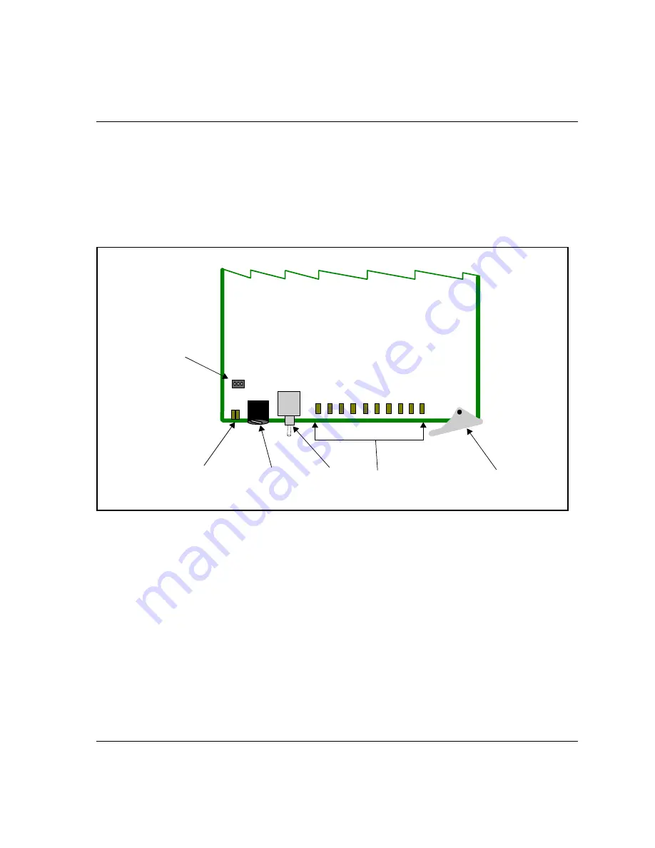
Figure 1-1

 is a generic top-front view of a typical 6800

+

 module and 

shows the general location of standard LEDs, controls, and jumpers.

Figure 1-1. 

Typical 6800

+

 Module

Table 1-1 on page 4

 briefly describes generic 6800

+

 LEDs, switches, 

and jumpers. See 

“Card-Edge and Parameter Operation” on page 21

 for 

more information on specific QSEE6800

+

H module controls, LEDs, 

and jumpers.

Module 

status 

LED 

Hex switch 

(mode select 

rotary switch)

Navigation 

toggle 

switch

Status 

LEDs

Remote/local 

control jumper

Extractor 

handle

Summary of Contents for QSEE6800 Plus H

Page 1: ...QSEE6800 H Signal Monitor Video and Thumbnail Streamer Installation and Operation Manual Edition A 175 000328 00...

Page 2: ......

Page 3: ...Edition A November 2006 QSEE6800 H Signal Monitor Video and Thumbnail Streamer Installation and Operation Manual...

Page 4: ...Web SuiteView TitleMotion UNIFRAME Velocity VelocityHD VideoCarte Videotek and X75 are trademarks of Harris Corporation which may be registered in the United States Canada and or other countries All o...

Page 5: ...ix Product Servicing ix Returning a Product ix Restriction on Hazardous Substances RoHS Compliance x Waste from Electrical and Electronic Equipment WEEE Compliance xi Safety xii Safety Terms and Symbo...

Page 6: ...ng Factory Default Parameter Settings 22 Reading Software and Hardware Versions 22 Using QSEE6800 H Card Edge Controls 23 Setting QSEE6800 Remote Control Parameters 26 QSEE6800 H Input Parameters 29 S...

Page 7: ...ng Temperature 60 Appendix A Communication and Control Troubleshooting Tips Overview 61 General Troubleshooting Steps 62 Software Communication and Control Issues 62 Pilot Lite Fails to Communicate wi...

Page 8: ...vi QSEE6800 H Installation and Operation Manual Contents Index Keywords 67...

Page 9: ...for the QSEE6800 H Signal Monitor Video and Thumbnail Streamer Audience This manual is written for engineers technicians and operators responsible for installation setup maintenance and or operation...

Page 10: ...bo boxes menus submenus windows lists and selection names Italics Indicates E mail addresses the names of books or publications and the first instances of new terms and specialized words that need emp...

Page 11: ...r field servicing All hardware upgrades modifications or repairs require you to return the modules to the Customer Service center Returning a Product In the unlikely event that your product fails to o...

Page 12: ...cycling The Directive took effect on July 1 2006 and it refers to the following hazardous substances Lead Pb Mercury Hg Cadmium Cd Hexavalent Chromium Cr V1 Polybrominated Biphenyls PBB Polybrominated...

Page 13: ...users will be required to recycle electrical and electronic equipment at end of its useful life and may not dispose of the equipment in landfills or by using other unapproved methods Some EU member st...

Page 14: ...product relies on forced air cooling it is recommended that all obstructions to the air flow be removed prior to mounting the frame in the rack If this product has a provision for external earth groun...

Page 15: ...ideo signal It collects and presents monitored data alarms audio level data and thumbnails over Ethernet to the CCS Navigator or Pilot software interface Thumbnails of up to eight inputs per module ca...

Page 16: ...als View at up to two frames per second Configure thumbnail resolution 3 preset resolutions for SD and 3 preset sizes for HD with an aspect ratio fixed at 4 3 or 16 9 based on video input format Selec...

Page 17: ...andard LEDs controls and jumpers Figure 1 1 Typical 6800 Module Table 1 1 on page 4 briefly describes generic 6800 LEDs switches and jumpers See Card Edge and Parameter Operation on page 21 for more i...

Page 18: ...rs Navigation toggle switch This switch navigates up and down through the available control parameters Up Decrease Down Increase Status LEDs These LEDs indicate varying states functions See Using QSEE...

Page 19: ...shows the triple slot back connectors used by the QSEE6800 H when installed in an FR6802 frame Figure 1 2 QSEE6800 H Back Connector Note The inputs are all independent you can connect any standard to...

Page 20: ...SD in 7 HD SD equalizer deserializer SDI HD SDin 6 HD SD equalizer deserializer SDI HD SD in 5 HD SD equalizer deserializer SDI HD SD in 4 HD SD equalizer deserializer SDI HD SD in 3 HD SD equalizer d...

Page 21: ...Firmware on page 14 Adding a License Key for MPEG 4 Streaming on page 20 See the FR6802 Frame Installation and Operation Manual for information about installing and operating an FR6802 frame and its...

Page 22: ...the maximum allowable power ratings for 6800 frames Note the given maximums before installing any 6800 modules in your frame Table 2 1 Maximum Power Ratings for 6800 Frames 6800 Frame Type Max Frame...

Page 23: ...in the original packaging materials for possible re use See Unpacking Shipping Information on page ix for information about returning a product for servicing Checking the Packing List Note Contact you...

Page 24: ...or handle Figure 2 1 shows the standard location of the CJ1 jumper 2 Place a jumper on pins 1 and 2 to set the module for Remote control or pins 2 and 3 to set the module for Local control See Figure...

Page 25: ...ng both front and rear modules ensure that the back module is installed first before plugging in the front module See the FR6800 Frame Installation and Operation Manual for information about installin...

Page 26: ...work QSEE6800 Configuration on page 12 Dual Network QSEE6800 H Configuration on page 13 Single Network QSEE6800 Configuration A single network configuration as shown in Figure has both control and mon...

Page 27: ...bly monitor up to 24 QSEE6800 H modules without SNMP enabled or 20 QSEE6800 H modules if SNMP is enabled Table 2 3 Maximum Number of QSEE6800 H Modules Per Configuration Configuration Description With...

Page 28: ...o ensure that you upload the correct files to the intended module In the unlikely event that an upgrade fails the module may not respond to controls and will appear to be non functional In that event...

Page 29: ...ect one or more devices and then click OK to close the Add Device dialog box You can only add one unit from each IP address All items in a frame have the same IP address The selected devices appear in...

Page 30: ...close the Software Upgrade window continue with other tasks or switch to the Progress tab to view the status of the transfers 9 Click on the Log tab and look at the Progress column to ensure that all...

Page 31: ...mware starting with step 3 of Upgrading the Firmware on page 13 Correcting a Failed Upgrading Procedure Firmware upgrades may fail in the event of network interruptions power failures or if files were...

Page 32: ...s on a Typical Card Edge 2 Set the hex switch to F 3 While pressing the navigation toggle switch down reinsert the module into the frame 4 Download the most recent appropriate upgrade package from our...

Page 33: ...eld enter 1 0 slotnumber Where for example 1 0 5 would refer to the module in slot 5 of the frame 9 Close the window CAUTION Do not make changes in the last field located above and to the right of the...

Page 34: ...e device has rebooted 16 Wait 30 seconds Your upgrade procedure is complete Adding a License Key for MPEG 4 Streaming To enter a license key to activate MPEG 4 streaming your CCS software must be in C...

Page 35: ...CCS Operation on page 41 See the following documents for information on how to operate this product remotely Pilot Lite User Manual for serial interface CCS Pilot CoPilot Navigator NUCLEUS or RCP CCS...

Page 36: ...its factory default settings you can either reset each parameter individually or do a global recall following this procedure 1 Rotate the hex switch to the global recall parameter F 2 Toggle the navi...

Page 37: ...view or set 2 Toggle the navigation switch to select and set the value of the chosen parameter Figure 3 2 on page 33 lists all of the card edge parameters for QSEE6800 H Legend Bold option Indicates t...

Page 38: ...4 STATUS 5 Channel 5 STATUS 6 Channel 6 STATUS 7 Channel 7 STATUS 8 Channel 8 On Signal is present Off Signal is not present Flashing Signal is present but with an alarm 1 Streaming Option Selects th...

Page 39: ...l for the given channel The LED indicates the selected size Options STATUS 1 Off STATUS 2 Low STATUS 3 Medium STATUS 4 High Read only indicators STATUS 5 Present STATUS 6 on HD off SD STATUS 7 Present...

Page 40: ...d cannot be used to select controls Table 3 2 Parameter Options QSEE6800 H Modules Remote Control Only Parameter Name1 Function Options Network IP Address Specifies the module s IP address String Init...

Page 41: ...hannel 6 Channel 7 Channel 8 MPEG4 Audio Source Selects one of the input audio pairs that will accompany the MPEG 4 output No Audio Group 1 Pair 1 Group 1 Pair 2 Group 2 Pair 1 Group 2 Pair 2 Group 3...

Page 42: ...he quality 1 to 10 5 Fixed Bit Rate Determines the bitrate of the MPEG 4 output 200kbps 300kbps 400kbps 500kbps 600kbps 700kbps 800kbps 900kbps 1000kbps 1 These parameters are only available from a re...

Page 43: ...it will appear on other QSEE6800 H displays String Thumbnail Resolution Determines the size of the thumbnail that will be output on this Control window Disable Low Medium High Rate Determines the ref...

Page 44: ...98 525 625 Audio Meter Determines which audio inputs are used for the audio meters on the thumbnail No Audio Group 1 Pair 1 Group 1 Pair 2 Group 2 Pair 1 Group 2 Pair 2 Group 3 Pair 1 Group 3 Pair 2 G...

Page 45: ...00 level 102 Chrominance Low Threshold Sets the threshold below which the SDI Chroma Low alarm is triggered 0 to 15 of nominal 100 level 0 Chrominance Peak Threshold Sets the threshold at which excess...

Page 46: ...dBFS SDI Embedded Audio Ch 2 Average Level SDI Embedded Audio Ch 3 Average Level SDI Embedded Audio Ch 4 Average Level SDI Embedded Audio Ch 5 Average Level SDI Embedded Audio Ch 6 Average Level SDI E...

Page 47: ...reference Figure 3 2 shows the general location of the monitoring LEDs on a generic 6800 module Figure 3 2 Location of QSEE6800 H LEDs Figure 3 3 LED Positions The status LEDs on the QSEE6800 H modul...

Page 48: ...larms appear on the QSEE6800 H Input Control windows All alarms can be enabled or disabled so you can choose which alarms to monitor Each alarm is configurable with the following features A Priority s...

Page 49: ...s been addressed When an SQM alarm appears in the QSEE6800 H the card edge Module Status LED will turn red SQM alarm names thresholds and other controls appear in Pilot and Navigator software only SQM...

Page 50: ...If this option is set to 0 and the alarm condition exists for any period of time the alarm will trigger Clear s Decide how long the alarm condition must abate before the alarm to be turned off Choose...

Page 51: ...tandard definition video signal Enabled 1 2 0 2 0 SDI CRC Error Reports recurring CRC errors in the high definition video signal Enabled 1 2 0 2 0 SDI Loss of Video Reports that active HD or SD video...

Page 52: ...rominance Low Threshold parameter Enabled 1 30 0 2 0 SDI Video Black Reports that the HD or SD video level does not exceed the level defined by the Video Black Threshold parameter Enabled 6 240 0 2 0...

Page 53: ...h 01 to 16 peak Detects that the peak audio level meets or exceeds the limit set in the Peak Audio Threshold parameter Enabled 1 30 0 2 0 SDI Embedded Ch 01 to 16 Loss of Sound Detects that the audio...

Page 54: ...arms Table 3 10 Data Alarms Alarm Name Alarm Description Alarm Option Default Settings Enable Disable Priority Trigger sec Clear sec SDI D_VITC Missing Reports that the D VITC signal is not detected o...

Page 55: ...gered an alarm This chapter assumes a basic knowledge of how to use CCS software See the Pilot or Navigator user guides and online help for detailed information on such functions as discovery changing...

Page 56: ...EG 4 Streaming To enter a license key to activate MPEG 4 streaming your CCS Software must be in Control mode Follow these steps 1 Select the QSEE6800 module in the Navigation pane right click and sele...

Page 57: ...EE6800 Module With Inputs After discovery your CCS software will recognize the different inputs to the QSEE6800 module It will retain the module name signal standard and module ID If the input changes...

Page 58: ...SEE6800 module in the Navigation pane The QSEE6800 control window has three tabs Stream tab see Setting QSEE6800 Remote Control Parameters on page 26 Display tab see Figure 4 2 Network tab see Multica...

Page 59: ...the line that is analyzed by the waveform or vectorscope set the Line Number parameter in the sub device s Control window To view a larger waveform or vectorscope double click on the image A pop up w...

Page 60: ...t The Multicast TTL Time to live parameter determines how many network switches can exist between your device in this case a QSEE6800 module and your client Normally you should leave this setting at i...

Page 61: ...3 on page 29 for more information The Parameters tab contains SQM parameters for the QSEE6800 input See Table 3 4 on page 31 for more information The Alarms tab contains on this page are described in...

Page 62: ...dividual input choose it and then click OK To add all the inputs for a QSEE6800 H module choose the module itself and then click OK You can only select one item at a time To add another item click Add...

Page 63: ...iewing area that it will be seen on Otherwise it will be cropped or will leave blank areas 8 Click Finish Your page is built Switch to Control mode to view your page or stay in Build mode to add or ed...

Page 64: ...ming Player Options Option Function Name Enter a label that will appear on the Graphical Navigation page only by default the name is a combination of the module name and input UMD ID Use name from mod...

Page 65: ...ures in a Graphical Navigation page that they have in a Control window For more information on these features see Controlling QSEE6800 H Modules in Pilot or Navigator on page 44 By default wizard gene...

Page 66: ...e video from that input Alarms Monitoring In addition to the diagnostics window alarms are indicated on the borders for both thumbnails and MPEG 4 streaming video on Graphical Navigation pages Figure...

Page 67: ...e 40 Launching the QuickTime Player Outside Your CCS Software You may need to launch a QuickTime player independent of your CCS Pilot or Navigator software for example to listen to audio There are two...

Page 68: ...module You can leave the Initial Directory field blank 7 Click OK to close the Action Properties dialog box Close the Object Properties window by clicking the X in the top right corner When you enter...

Page 69: ...iles quicktime quicktimeplayer exe or the complete path to your QuickTime Player installation if it differs from the above Arguments rtsp IP Address 554 streaming replace IP Address by the IP address...

Page 70: ...56 QSEE6800 H Installation and Operation Manual Chapter 4 CCS Operation...

Page 71: ...nual 57 Chapter 5 Specifications Overview The following specification tables appear in this chapter Video Input on page 58 Video Output on page 59 Power Consumption on page 60 Specifications and desig...

Page 72: ...BNC per IEC 169 8 Impedance 75 Return loss 15 dB typical up to 1485 MHz Equalization Adaptive cable equalization for up to 388 ft 100 m typical of Belden 8281 or 492 ft 150 m typical of Belden 1694A...

Page 73: ...cations Connector RJ 45 Thumbnail JPEG Thumbnail resolution SD Low 128 96 Medium 192 144 High 256 192 Thumbnail resolution HD Low 128 72 Medium 192 108 High 256 144 Refresh rate Up to 2 frames per sec...

Page 74: ...ation Manual Chapter 5 Specifications Power Consumption Operating Temperature The operating temperature for QSEE6800 H modules is 41 to 113 F 5 to 45 C Table 5 5 Power Consumption Module Power Consump...

Page 75: ...ol Troubleshooting Tips Overview Find the following troubleshooting information in this appendix General Troubleshooting Steps on page 62 Software Communication and Control Issues on page 62 Hardware...

Page 76: ...if after following these initial steps you cannot resolve the issue To contact Customer Service see Contacting Customer Service on page 66 Software Communication and Control Issues Pilot Lite Fails t...

Page 77: ...r frame See your FR6802 Frame Installation and Operation Manual for more information on frame ID switch settings Null modem cable is not being used Between the PC running Pilot Lite and the FR6802 fra...

Page 78: ...discovery is started too soon after frame power up Pilot Lite will not find all the installed modules Refresh Pilot Lite File Refresh and ensure that installed modules are fully powered up first befo...

Page 79: ...module in its slot in the frame Does the Control window indicate the device is ready The device may be powered off or disconnected from the network Pilot Lite Status Bar Reports Not Ready Pilot Lite r...

Page 80: ...s Not Seem to Work on page 66 Frames Fail to Communicate with the PC after a Power Failure You must exit the software and restart after the frame recovers from its power failure To restore communicati...

Page 81: ...ication not responding 65 Audio alarms 39 B Back connector 5 9 Bank select 24 BNC connector 58 C Card edge parameters 24 CCS application 65 Clear duration alarms 36 Clip 26 Closed captioning not prese...

Page 82: ...33 parameter indicators 24 positions on module 33 License key 20 Local control 65 jumper 4 M Making connections 12 Manual information vii viii Maximum allowable power ratings 8 Mode select rotary swit...

Page 83: ...alarms 35 Product description 2 Product servicing ix Q QuickTime monitoring 54 R Reboot device 66 Recall default parameter settings 22 Remote control 65 jumper 3 parameters 26 Removing modules 11 Retu...

Page 84: ...emarks ii Trigger duration alarms 36 Troubleshooting 61 66 communication 63 control 65 installation 66 U Unpacking modules ix 9 Upgrading module software 14 20 Usable slots 8 V Vector display mode 45...

Page 85: ......

Page 86: ...tal Way Mason OH USA 45040 Tel 1 513 459 3400 www broadcast harris com Copyright 2006 Harris Corporation Harris and Leitch are registered trademarks of Harris Corporation Trademarks and tradenames are...

Reviews: