2-10
RF-7800B
SYSTEM SETUP AND TEARDOWN
R
2.5.3
Cable Connections
For connector pinouts, refer to
for some installation options. Refer to
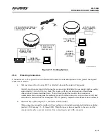
for detailed connection information. In general, install the following:
•
Data cable between BGAN terminal and computer
•
Power cable between BGAN terminal and power source. For the RF-7800B-DU024 using the BGAN, AC
to DC Power Supply Assembly with plug kit, use one of the following plugs:
•
ST-5: United States, Canada, Japan, China, Taiwan
•
ST-7: United Kingdom, Hong Kong, Singapore
•
ST-9: Germany, France, Indonesia, Korea
•
ST-16: Australia, New Zealand, China
•
ST-9C: European Union, United Arab Emirates, South America
NOTE
Do not use excessive force when connecting the data and
power cables to the BGAN terminal. Connectors are keyed.
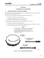
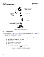
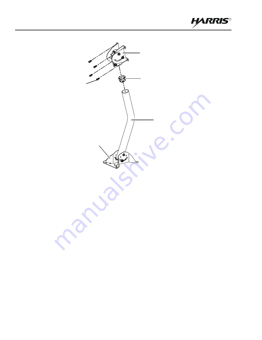
Figure 2-10. Fixed Mount Option
UNIVERSAL
MOUNT
BUBBLE LEVEL INDICATOR
AND HOLDER
SCREW, CAP,
HEX SOCKET,
1/4 - 20X1/2
(4 PLACES)
NOTE: USE CUSTOMER FURNISHED
MOUNTING HARDWARE FOR POLE
OR SURFACE MOUNT.
AZIMUTH CANISTER/INCLINE
BRACKET ASSEMBLY
CL-0365-4200-0013
Summary of Contents for RF-7800B-DUO24
Page 3: ......
Page 5: ......
Page 11: ...vi RF 7800B TABLE OF CONTENTS R This page intentionally left blank...
Page 17: ...RF 7800B R This page intentionally left blank...
Page 27: ...1 10 RF 7800B GENERAL INFORMATION R This page intentionally left blank...
Page 53: ...3 14 RF 7800B OPERATION R This page intentionally left blank...
Page 61: ...4 8 RF 7800B CONFIGURATION R Figure 4 4 BGAN Terminal Configuration...
Page 67: ...4 14 RF 7800B CONFIGURATION R Figure 4 8 BGAN Terminal IP Automatic Network Connections...
Page 77: ...4 24 RF 7800B CONFIGURATION R This page intentionally left blank...

