3-2
RF-7800W
SYSTEM ADMINISTRATION AND CONFIGURATION
R
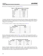
Default values of IP management interfaces are shown in
* In addition to the default static IP Address, the radio uses ZeroConf technologies to automatically self-assign a
second unique IP Address and a hostname and to advertise the presence of its management interfaces (HTTP and
SSH). The ZeroConf services are intended solely to ease initial configuration and are disabled once an operator
configures a new static IP Address.
The Console data port interface uses RS-422 with port settings as shown in
.
The factory default login credentials are shown in
. The “Admin” user group is meant to be used for
changing the configuration of the radio. The “User” user group has access to less configuration permissions, but is
simpler to use. The “Monitor” user group is meant to be used by machine interfaces that only need read access to
small set of commands.
Changes to the radio's configuration are not applied until an “apply” or “save” command is issued in any of the
management interfaces. Even after applying the changes to the active configuration, the changes must be saved to
the on-board memory by issuing a “save” command. If the configuration is applied but not saved, a power loss or
an intentional reboot will cause any changes made since the last “save” to be lost.
Table 3-1. IP Management Interface Parameters
Parameter
Default Value
IP Address
192.168.26.2*
HTTP
Enabled
HTTPS
Enabled
Telnet
Enabled
SSH
Enabled
SNMP
None
Table 3-2. Console Port Settings
Port Parameter
Value
Speed (baud rate)
115200
Data Bits
8
Stop Bits
1
Parity
None
Flow Control
None
Table 3-3. Factory Default Login Credentials
User Name
Password
User Group
admin
admin
admin
user
user
user
monitor
monitor
monitor
Summary of Contents for RF-7800W-OU470
Page 3: ......
Page 11: ...viii RF 7800W TABLE OF CONTENTS R This page intentionally left blank...
Page 15: ...xii RF 7800W SAFETY SUMMARY R This page intentionally left blank...
Page 29: ...1 14 RF 7800W GENERAL INFORMATION R This page intentionally left blank...
Page 38: ...2 9 RF 7800W SYSTEM INSTALLATION R Figure 2 5 Antenna Alignment...
Page 39: ...2 10 RF 7800W SYSTEM INSTALLATION R This page intentionally left blank...
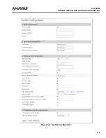
Page 46: ...3 7 RF 7800W SYSTEM ADMINISTRATION AND CONFIGURATION R Figure 3 4 System Configuration...
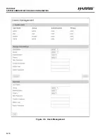
Page 49: ...3 10 RF 7800W SYSTEM ADMINISTRATION AND CONFIGURATION R Figure 3 6 Users Management...
Page 75: ...3 36 RF 7800W SYSTEM ADMINISTRATION AND CONFIGURATION R Figure 3 21 Subscriber Link Status...
Page 77: ...3 38 RF 7800W SYSTEM ADMINISTRATION AND CONFIGURATION R Figure 3 22 Subscriber Links...
Page 81: ...3 42 RF 7800W SYSTEM ADMINISTRATION AND CONFIGURATION R Figure 3 24 File Management...
Page 85: ...3 46 RF 7800W SYSTEM ADMINISTRATION AND CONFIGURATION R This page intentionally left blank...
Page 89: ...4 4 RF 7800W DEPLOYMENT SCENARIOS R This page intentionally left blank...
Page 95: ...5 6 RF 7800W TROUBLESHOOTING AND MAINTENANCE R This page intentionally left blank...
Page 110: ...B 1 RF 7800W APPENDIX B R APPENDIX B EU DECLARATION OF CONFORMITY...
Page 111: ...B 2 RF 7800W APPENDIX B R This page intentionally left blank...


