1-9
RF-7800W
GENERAL INFORMATION
R
•
The Tx Power must be reduced in order to achieve Equivalent Isotropically Radiated Power (EIRP)
limits. Refer to
.
g.
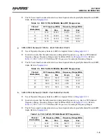
5.250-5.350 GHz band (U-NII-2A: Part 15.401-Part 15.407)
•
Use of Dynamic Frequency Selection (DFS) is required. Refer to
.
•
In order to ensure that the radio remains on designated frequencies, e.g. due to a DFS-induced
frequency change, Frequency Ranges must be defined. Refer to
. Refer to
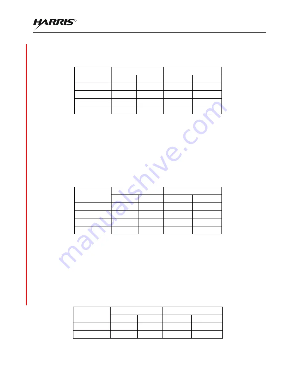
FCC 5.250-5.350 GHz Band RF Frequencies
for example Frequency Ranges.
•
The Tx Power must be reduced in order to achieve Equivalent Isotropically Radiated Power (EIRP)
limits. Refer to
.
h.
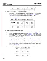
5.470-5.725 GHz band (U-NII-2C: Part 15.401-Part 15.407)
•
Use of Dynamic Frequency Selection (DFS) is required. Refer to
.
•
In order to ensure that the radio remains on designated frequencies, e.g. due to a DFS-induced
frequency change, Frequency Ranges must be defined. Refer to
. Refer to
FCC 5.470-5.725 GHz Band RF Frequencies
for example Frequency Ranges.
•
The Tx Power must be reduced in order to achieve Equivalent Isotropically Radiated Power (EIRP)
limits. Refer to
.
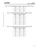
Table 1-4. FCC 5.150-5.250 GHz Band RF Frequencies
Channel
Width (MHz)
RF Frequency (MHz)
Frequency Range (MHz)
Min
Max
Begin
End
5
5170
5242.5
5167.5
5245
10
5170
5240.5
5165
5245.5
20
5170
5235.5
5160
5245.5
40
5170
5230
5150
5250
Table 1-5. FCC 5.250-5.350 GHz Band RF Frequencies
Channel
Width (MHz)
RF Frequency (MHz)
Frequency Range (MHz)
Min
Max
Begin
End
5
5252.5
5330
5250
5332.5
10
5255
5330
5250
5335
20
5260
5330
5250
5340
40
5270
5328
5250
5348
Table 1-6. FCC 5.470-5.725 GHz Band RF Frequencies
Channel
Width (MHz)
RF Frequency (MHz)
Frequency Range (MHz)
Min
Max
Begin
End
5
5490
5700
5487.5
5702.5
10
5490
5700
5485
5705
Summary of Contents for RF-7800W-OU470
Page 3: ......
Page 11: ...viii RF 7800W TABLE OF CONTENTS R This page intentionally left blank...
Page 15: ...xii RF 7800W SAFETY SUMMARY R This page intentionally left blank...
Page 29: ...1 14 RF 7800W GENERAL INFORMATION R This page intentionally left blank...
Page 38: ...2 9 RF 7800W SYSTEM INSTALLATION R Figure 2 5 Antenna Alignment...
Page 39: ...2 10 RF 7800W SYSTEM INSTALLATION R This page intentionally left blank...
Page 46: ...3 7 RF 7800W SYSTEM ADMINISTRATION AND CONFIGURATION R Figure 3 4 System Configuration...
Page 49: ...3 10 RF 7800W SYSTEM ADMINISTRATION AND CONFIGURATION R Figure 3 6 Users Management...
Page 75: ...3 36 RF 7800W SYSTEM ADMINISTRATION AND CONFIGURATION R Figure 3 21 Subscriber Link Status...
Page 77: ...3 38 RF 7800W SYSTEM ADMINISTRATION AND CONFIGURATION R Figure 3 22 Subscriber Links...
Page 81: ...3 42 RF 7800W SYSTEM ADMINISTRATION AND CONFIGURATION R Figure 3 24 File Management...
Page 85: ...3 46 RF 7800W SYSTEM ADMINISTRATION AND CONFIGURATION R This page intentionally left blank...
Page 89: ...4 4 RF 7800W DEPLOYMENT SCENARIOS R This page intentionally left blank...
Page 95: ...5 6 RF 7800W TROUBLESHOOTING AND MAINTENANCE R This page intentionally left blank...
Page 110: ...B 1 RF 7800W APPENDIX B R APPENDIX B EU DECLARATION OF CONFORMITY...
Page 111: ...B 2 RF 7800W APPENDIX B R This page intentionally left blank...

