2-2
RF-7800W
SYSTEM INSTALLATION
R
2.1.4
Co-location
Radio co-location on a single mast or tower system is sometimes unavoidable. A number of strategies can be
employed to reduce the possibility of interference between radios. Higher gain antennas typically have a narrower
beamwidth, which can help increase the signal to noise ratio (SNR) if they are not pointed in the same direction. If
possible, co-located radios should use operating frequencies that are at least one full channel width away from each
other.
2.2
INSTALLATION REQUIREMENTS
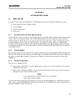
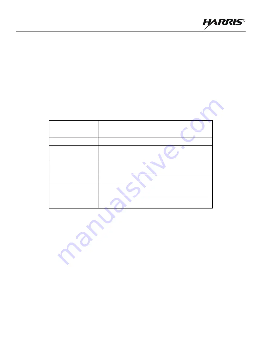
. In preparation for installing a RF-7800W HCLOS Radio system, the following items that are not
included are required.
These items are also not included, but are needed in order to maximize equipment performance:
•
Outdoor rated, shielded Category 5e (or higher) Ethernet cable with shielded RJ-45 connectors. Amphenol
RJF6B backshells (key code 'A') should be added to any cables used to protect the radio's internal from
moisture. (Harris PN 12069-0030-Axxx and 12069-0031-Axxx)
•
Dual-linear (V/H) polarized antennas in order to operate at full throughput capacity. (Harris PN RF-7800W-
AT2XX)
The installation site should be free from major twist or sway under wind loading. A higher mounting location will
help guarantee better Line of Sight (LOS) conditions, but can increase the risk of damage due to lightning. The
mounting location should also provide a clear view of the sky for GPS, if required.
2.3
PRE-INSTALLATION CONFIGURATION
Time can be saved and hassle avoided by configuring all of the RF-7800W radios before they are permanently
installed. Two Ethernet cables and a computer with an Ethernet port are required for this step.
2.3.1
Connecting to a Radio
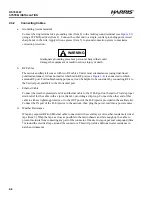
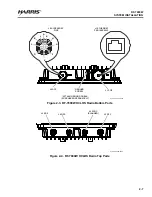
a.
Connect an Ethernet cable between the J1 PoE port in the radio and the OUT port on the PoE injector,
allowing up to three (3) minutes for the radio to boot.
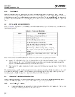
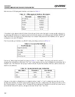
Table 2-1. Tools and Materials
Item
Description
1
7/16” Open or Close Ended Wrench
2
7/16” Socket Wrench
3
#2 Drive Phillips-tip Screwdriver
4
Cable Ties, Zip Ties, or Tie-Wraps
5
Silicone Grease (Dow Corning DC-5 or similar
corrosion preventative compound)
6
Electrical Tape (3M Scotch Super 33+ or similar)
7
Polyurethane Sealant (Vulkem 116, Sikaflex 201, or
similar)
8
Ground Wire - 10 AWG min, with a 10/32” (M5) ring
terminal
Summary of Contents for RF-7800W-OU470
Page 3: ......
Page 11: ...viii RF 7800W TABLE OF CONTENTS R This page intentionally left blank...
Page 15: ...xii RF 7800W SAFETY SUMMARY R This page intentionally left blank...
Page 29: ...1 14 RF 7800W GENERAL INFORMATION R This page intentionally left blank...
Page 38: ...2 9 RF 7800W SYSTEM INSTALLATION R Figure 2 5 Antenna Alignment...
Page 39: ...2 10 RF 7800W SYSTEM INSTALLATION R This page intentionally left blank...
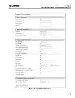
Page 46: ...3 7 RF 7800W SYSTEM ADMINISTRATION AND CONFIGURATION R Figure 3 4 System Configuration...
Page 49: ...3 10 RF 7800W SYSTEM ADMINISTRATION AND CONFIGURATION R Figure 3 6 Users Management...
Page 75: ...3 36 RF 7800W SYSTEM ADMINISTRATION AND CONFIGURATION R Figure 3 21 Subscriber Link Status...
Page 77: ...3 38 RF 7800W SYSTEM ADMINISTRATION AND CONFIGURATION R Figure 3 22 Subscriber Links...
Page 81: ...3 42 RF 7800W SYSTEM ADMINISTRATION AND CONFIGURATION R Figure 3 24 File Management...
Page 85: ...3 46 RF 7800W SYSTEM ADMINISTRATION AND CONFIGURATION R This page intentionally left blank...
Page 89: ...4 4 RF 7800W DEPLOYMENT SCENARIOS R This page intentionally left blank...
Page 95: ...5 6 RF 7800W TROUBLESHOOTING AND MAINTENANCE R This page intentionally left blank...
Page 110: ...B 1 RF 7800W APPENDIX B R APPENDIX B EU DECLARATION OF CONFORMITY...
Page 111: ...B 2 RF 7800W APPENDIX B R This page intentionally left blank...

