2-3
RF-7800W
SYSTEM INSTALLATION
R
b.
Connect an Ethernet cable between the IN port on the PoE injector and computer.
c.
Configure the computer's IP address so that it is different than the radio's default IP address
(192.168.26.2), but also on the same subnet (255.255.255.0). The address should be in the range
192.168.26.1 - 192.168.26.254.
d.
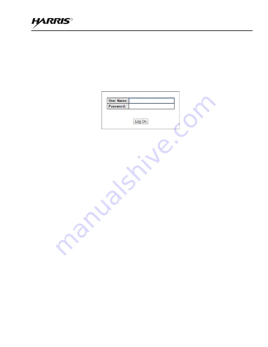
Open a web browser to the radio's address and log in using the default credentials (admin/admin).
2.3.2
Configure the Subscriber Stations
a.
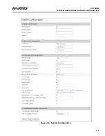
Select System Configuration, change the IP Address from the default to a unique value, and select
Apply & Save All. This ensures that each radio can be properly accessed once wireless Links establish.
b.
Reconfigure the computer's IP Address if necessary (e.g. if the radio IP Address was set outside of the
range 192.168.26.1-192.168.26.254).
c.
Open a web browser to the radio's new address and log in.
d.
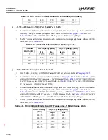
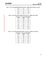
Select Wireless Configuration, configure the Frequency and Channel Size based on frequency
availability, and select Apply & Save All. These settings must be the same for all radios that are to be
linked. See
.
e.
Change the Tx Power, if necessary, and select Apply & Save All.
f.
Perform the System and Wireless Configuration for all other SS radios, recording each radio's MAC
address if using Normal Links as they will be needed when configuring the SC radio. Otherwise, ensure
that the STID and STID Password match those of the SC radio if using Link templates.
NOTE
STID Password defaults to “default”.
2.3.3
Configure the Sector Controller
a.
Select System Configuration, change the IP Address from the default to a unique value, and select
Apply & Save All. This ensures that each radio can be properly accessed once wireless Links
establish.See
.
b.
Reconfigure the computer's IP Address if necessary (e.g. if the radio IP Address was set outside of the
range 192.168.26.1-192.168.26.254).
c.
Open a web browser to the radio's new address and log in.
d.
Select Wireless Configuration and change the System Mode to SPMP SC. See
Figure 2-1. Log In
Summary of Contents for RF-7800W-OU470
Page 3: ......
Page 11: ...viii RF 7800W TABLE OF CONTENTS R This page intentionally left blank...
Page 15: ...xii RF 7800W SAFETY SUMMARY R This page intentionally left blank...
Page 29: ...1 14 RF 7800W GENERAL INFORMATION R This page intentionally left blank...
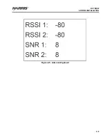
Page 38: ...2 9 RF 7800W SYSTEM INSTALLATION R Figure 2 5 Antenna Alignment...
Page 39: ...2 10 RF 7800W SYSTEM INSTALLATION R This page intentionally left blank...
Page 46: ...3 7 RF 7800W SYSTEM ADMINISTRATION AND CONFIGURATION R Figure 3 4 System Configuration...
Page 49: ...3 10 RF 7800W SYSTEM ADMINISTRATION AND CONFIGURATION R Figure 3 6 Users Management...
Page 75: ...3 36 RF 7800W SYSTEM ADMINISTRATION AND CONFIGURATION R Figure 3 21 Subscriber Link Status...
Page 77: ...3 38 RF 7800W SYSTEM ADMINISTRATION AND CONFIGURATION R Figure 3 22 Subscriber Links...
Page 81: ...3 42 RF 7800W SYSTEM ADMINISTRATION AND CONFIGURATION R Figure 3 24 File Management...
Page 85: ...3 46 RF 7800W SYSTEM ADMINISTRATION AND CONFIGURATION R This page intentionally left blank...
Page 89: ...4 4 RF 7800W DEPLOYMENT SCENARIOS R This page intentionally left blank...
Page 95: ...5 6 RF 7800W TROUBLESHOOTING AND MAINTENANCE R This page intentionally left blank...
Page 110: ...B 1 RF 7800W APPENDIX B R APPENDIX B EU DECLARATION OF CONFORMITY...
Page 111: ...B 2 RF 7800W APPENDIX B R This page intentionally left blank...

