2-6
RF-7800W
SYSTEM INSTALLATION
R
2.4.2
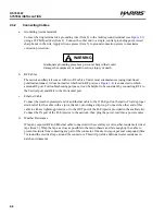
Connecting Cables
a.
Grounding (recommended)
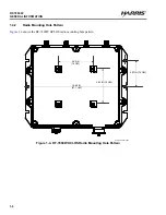
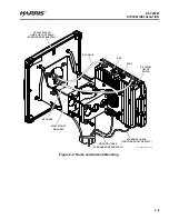
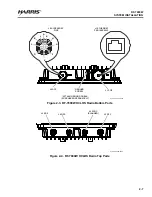
Connect the ring terminal of a grounding wire (Item 8) to the radio's ground terminal (see
)
using a #2 Phillips driver (Item 3). Connect the other end to a single, central grounding point. Avoid
sharp bends in the wire. Apply silicone grease (Item 5) to ground connection points to maximize
corrosion protection.
WARNING
Inadequate grounding presents a personnel hazard that could
damage the equipment or result in serious injury or death.
b.
RF Cables
The radio's ancillary kit comes with two RF cables. Under most circumstances (using dual-linear
polarized antennas), it does not matter which radio RF port (see
antenna RF port. For troubleshooting purposes, it can be helpful to be consistent by connecting RF-1 to
the Vertical port and RF-2 to the Horizontal port.
c.
Ethernet Cable
Connect the weather-protected end of an Ethernet cable to the J1 PoE port on the radio. Provide proper
strain relief for the cable with a zip tie (Item 4), providing a drip loop. Connect the other end of this
cable to either a lightning protector, or to the OUT port of the PoE injector provided in the ancillary kit.
Connect the IN port of the PoE injector to the network, then plug the power cord into a power source.
d.
Weather Resistance
Wrap any exposed RF and Ethernet cable connectors with several layers of weather resistant electrical
tape (Item 6). Wrap the tape as close as possible to the radio chassis and far enough up the cable to
prevent moisture from contacting any part of the connector. If desired, wrap vapor seal compound (Item
7) around the electrical tape around the connectors. This will provide additional water resistance in
harsh environments.
Summary of Contents for RF-7800W-OU470
Page 3: ......
Page 11: ...viii RF 7800W TABLE OF CONTENTS R This page intentionally left blank...
Page 15: ...xii RF 7800W SAFETY SUMMARY R This page intentionally left blank...
Page 29: ...1 14 RF 7800W GENERAL INFORMATION R This page intentionally left blank...
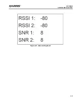
Page 38: ...2 9 RF 7800W SYSTEM INSTALLATION R Figure 2 5 Antenna Alignment...
Page 39: ...2 10 RF 7800W SYSTEM INSTALLATION R This page intentionally left blank...
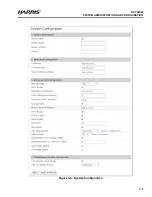
Page 46: ...3 7 RF 7800W SYSTEM ADMINISTRATION AND CONFIGURATION R Figure 3 4 System Configuration...
Page 49: ...3 10 RF 7800W SYSTEM ADMINISTRATION AND CONFIGURATION R Figure 3 6 Users Management...
Page 75: ...3 36 RF 7800W SYSTEM ADMINISTRATION AND CONFIGURATION R Figure 3 21 Subscriber Link Status...
Page 77: ...3 38 RF 7800W SYSTEM ADMINISTRATION AND CONFIGURATION R Figure 3 22 Subscriber Links...
Page 81: ...3 42 RF 7800W SYSTEM ADMINISTRATION AND CONFIGURATION R Figure 3 24 File Management...
Page 85: ...3 46 RF 7800W SYSTEM ADMINISTRATION AND CONFIGURATION R This page intentionally left blank...
Page 89: ...4 4 RF 7800W DEPLOYMENT SCENARIOS R This page intentionally left blank...
Page 95: ...5 6 RF 7800W TROUBLESHOOTING AND MAINTENANCE R This page intentionally left blank...
Page 110: ...B 1 RF 7800W APPENDIX B R APPENDIX B EU DECLARATION OF CONFORMITY...
Page 111: ...B 2 RF 7800W APPENDIX B R This page intentionally left blank...

