3-32
RF-7800W
SYSTEM ADMINISTRATION AND CONFIGURATION
R
3.9.3.2
Burst Rate
When adaptive modulation is not used, a single set of downlink and uplink burst rates must be configured. If the
burst rate is set too high for a given link budget, it will be difficult to initiate and maintain a reliable link. When
adaptive modulation is used, maximum and minimum downlink and uplink burst rates must be configured. The radio
will attempt to stay above the minimum, but will adapt to lower modulations if link conditions deteriorate. Refer to
.
3.9.4
Information Rate
The Committed Information Rate (CIR) defines a link's minimum required user data rate. The Peak Information Rate
(PIR) defines a link's maximum allowed user data rate. On a per-link basis, there are separate CIR and PIR values
for both the downlink and uplink. The SC uses these values to assist with prioritizing how much traffic is sent over
each link when there is not enough transmission time to get all data to all subscribers. The SC will attempt to ensure
that the CIR is met on all subscribers, but may be forced to proportionally scale them if link conditions deteriorate
and the burst rate is not able to support them.
Table 3-5. Burst Rates per Channel Width
Modulation/
Coding
Burst Rate per Channel Width
5 MHz
10 MHz
20 MHz
40 MHz
SISO/
MIMO-A
BPSK 1/2
2
4
8
17
QPSK 1/2
4
8
17
34
QPSK 3/4
6
12
25
51
16-QAM 1/2
8
17
34
68
16-QAM 3/4
12
25
51
102
64-QAM 2/3
17
34
68
136
64-QAM 5/6
21
42
85
170
256-QAM 3/4
25
51
102
204
256-QAM 7/8
29
59
119
238
MIMO-B
BPSK 1/2
4
8
17
34
QPSK 1/2
8
17
34
68
QPSK 3/4
12
25
51
102
16-QAM 1/2
17
34
68
136
16-QAM 3/4
25
51
102
204
64-QAM 2/3
34
68
136
272
64-QAM 5/6
42
85
170
340
256-QAM 3/4
51
102
204
408
256-QAM 7/8
59
119
238
476
GUI CLI SNMP
GUI CLI SNMP
Summary of Contents for RF-7800W-OU470
Page 3: ......
Page 11: ...viii RF 7800W TABLE OF CONTENTS R This page intentionally left blank...
Page 15: ...xii RF 7800W SAFETY SUMMARY R This page intentionally left blank...
Page 29: ...1 14 RF 7800W GENERAL INFORMATION R This page intentionally left blank...
Page 38: ...2 9 RF 7800W SYSTEM INSTALLATION R Figure 2 5 Antenna Alignment...
Page 39: ...2 10 RF 7800W SYSTEM INSTALLATION R This page intentionally left blank...
Page 46: ...3 7 RF 7800W SYSTEM ADMINISTRATION AND CONFIGURATION R Figure 3 4 System Configuration...
Page 49: ...3 10 RF 7800W SYSTEM ADMINISTRATION AND CONFIGURATION R Figure 3 6 Users Management...
Page 75: ...3 36 RF 7800W SYSTEM ADMINISTRATION AND CONFIGURATION R Figure 3 21 Subscriber Link Status...
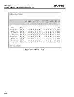
Page 77: ...3 38 RF 7800W SYSTEM ADMINISTRATION AND CONFIGURATION R Figure 3 22 Subscriber Links...
Page 81: ...3 42 RF 7800W SYSTEM ADMINISTRATION AND CONFIGURATION R Figure 3 24 File Management...
Page 85: ...3 46 RF 7800W SYSTEM ADMINISTRATION AND CONFIGURATION R This page intentionally left blank...
Page 89: ...4 4 RF 7800W DEPLOYMENT SCENARIOS R This page intentionally left blank...
Page 95: ...5 6 RF 7800W TROUBLESHOOTING AND MAINTENANCE R This page intentionally left blank...
Page 110: ...B 1 RF 7800W APPENDIX B R APPENDIX B EU DECLARATION OF CONFORMITY...
Page 111: ...B 2 RF 7800W APPENDIX B R This page intentionally left blank...

