4-2
RF-7800W
DEPLOYMENT SCENARIOS
R
4.2.2
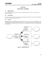
SPTP
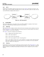
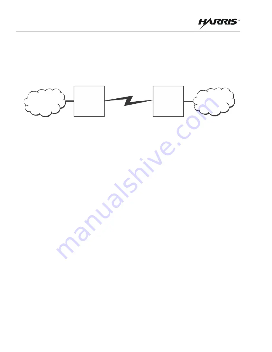
Simple Point to Point (SPTP) supports one SS at a time per SC. See
. Both radios must operate on the
same Frequency and Channel Width. While SPMP can be used with one SS, SPTP is optimized to operate with only
one SS and therefore has slightly different behavior.
4.3
ON-THE-MOVE
While the RF-7800W radio can operate On-the-Move with SPTP and SPMP, two mutually exclusive features
supported by SPMP (Multi-Hop and Roaming) provide better performance.
4.3.1
Multi-Hop
Multi-Hop allows SS to communicate directly with other SS in certain situations in order to maintain connectivity.
Refer to
. All radios must operate on the same Frequency and Channel Width. All SS and the SC
must be configured to use the same Link Template.
, the panels of the figure are described below:
Panel 1 - Multiple SS are linked directly to the SC.
Panel 2 - SS N relays through SS 2.
Panel 3 - SS N and SS 1 relay through SS 2.
Panel 4 - SS N relays through SS 1 and SS 1 relays through SS 2.
Panel 5 - SS 1 operates as a Failover SC, since the original SC is no longer accessible. When the original
SC becomes accessible again, the SS not acting as Failover SC would link to the SC and eventually the
Failover SC would revert to being an SS.
4.3.2
Roaming
Roaming allows SS to move between SC without losing network connectivity. Refer to
. All SC
must be connected to the same network via their Ethernet ports. SC which can see each other must be on different
Frequencies and may be on different Channel Widths. All SS and SC must be configured to use the same Link
Template.
Figure 4-2. SPTP Deployment
SPTP SC
FREQ: A
CH WID: X
SPTP SS
FREQ: A
CH WID: X
Summary of Contents for RF-7800W-OU470
Page 3: ......
Page 11: ...viii RF 7800W TABLE OF CONTENTS R This page intentionally left blank...
Page 15: ...xii RF 7800W SAFETY SUMMARY R This page intentionally left blank...
Page 29: ...1 14 RF 7800W GENERAL INFORMATION R This page intentionally left blank...
Page 38: ...2 9 RF 7800W SYSTEM INSTALLATION R Figure 2 5 Antenna Alignment...
Page 39: ...2 10 RF 7800W SYSTEM INSTALLATION R This page intentionally left blank...
Page 46: ...3 7 RF 7800W SYSTEM ADMINISTRATION AND CONFIGURATION R Figure 3 4 System Configuration...
Page 49: ...3 10 RF 7800W SYSTEM ADMINISTRATION AND CONFIGURATION R Figure 3 6 Users Management...
Page 75: ...3 36 RF 7800W SYSTEM ADMINISTRATION AND CONFIGURATION R Figure 3 21 Subscriber Link Status...
Page 77: ...3 38 RF 7800W SYSTEM ADMINISTRATION AND CONFIGURATION R Figure 3 22 Subscriber Links...
Page 81: ...3 42 RF 7800W SYSTEM ADMINISTRATION AND CONFIGURATION R Figure 3 24 File Management...
Page 85: ...3 46 RF 7800W SYSTEM ADMINISTRATION AND CONFIGURATION R This page intentionally left blank...
Page 89: ...4 4 RF 7800W DEPLOYMENT SCENARIOS R This page intentionally left blank...
Page 95: ...5 6 RF 7800W TROUBLESHOOTING AND MAINTENANCE R This page intentionally left blank...
Page 110: ...B 1 RF 7800W APPENDIX B R APPENDIX B EU DECLARATION OF CONFORMITY...
Page 111: ...B 2 RF 7800W APPENDIX B R This page intentionally left blank...

