Summary of Contents for STX-1B

Page 1: ...s dynamic program material A stereo audio peak limiter maintains Left Right L R and L R modulation levels within legal limits This built in limiter includes automatic 125 asymmetri cal switching to a...

Page 2: ...nda modern AM transmittermeas ured by a C QUAM modulation monitor Actual system performance wt I vary due to transmitterandantenna system performance SYSTEM FREQUENCY RESPONSE t 0 3 dB 50 Hz to 12 5 k...

Page 3: ...Quam s t reo demodul ator l r to Time Required Approximately four hours for the conversion and exciter realignment A full proof of performance is req ir ed after the conversion Procedure Audio Input...

Page 4: ...and P5 These components will not be reinstalled Solder jumper from center post of J3 to the center post of J4 Be careful not to fill the plug of J4 The preferred method is to wrap t he jumper around t...

Page 5: ...rate adjustment R44 set mid range 3 Check the setting of the carrier adjust control Rl4 located on the quadrature generator board This should be done by monitoring the depth of modulation of the IF ca...

Page 6: ...e 5 to lOdB of gain reduction as before Select the pattern to be aligned day or night The exciter should still be in mono Turn the transmitter on and monitor the modulation level on a mono monitor or...

Page 7: ...nel output of the stereo monitor Adjust the coarse delay rotary switch S1 or S2 for lowest distortion In the following order adjust the high frequency equalization R33 or R34 group delay R28 or R29 an...

Page 8: ...separation with little effect on distortion To use the Separation Corrector move t he jumpers J5 and J6 on the Peak Limiter Separation Corrector card to the l ower position The 12 potentiometers at t...

Page 9: ...y moving the jumpers JS and_J6 on the Peak Limiter Separation Corrector card to their upper position 7 The audio response of the system is a result of alignment of the Audio Output card and the Separa...

Page 10: ...Com AM 205 MJL I Page 8 _ Cl UC N 4 Z fZ o Z Z a I f o o a l6 N M w 0 I UN co U ll co I co 0 g t Q t ____ ____ Z a 1 0 _ I _ K K K K Go 5 5 2 a s 0 2 a 2 f a s r d T o I K w T ro 0 3 f I 0 _ 0 0 iZ ii...

Page 11: ...www SteamPoweredRadio Com l 0 2 H 0 H a J C C I C I C J 0 0 AM 205 MJL Page 9 e 10 R18 0 0 C 0 0 of Q 4 1 a l fY 1rh 3 FiG A...

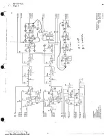
Page 12: ...www SteamPoweredRadio Com M 205 MJL Page 10 11 a q u 0 I co I co...

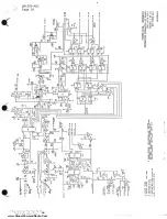
Page 13: ...www SteamPoweredRadio Com AM 205 M JL Page 11 J 0 O 0 __ i a 4 0 i N 7 CID CID...

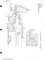
Page 14: ...www SteamPoweredRadio Com AM 205 MJL Page 12 0 a ca C w I co _ C 0 Cl I o C J 0 0 a...

Page 15: ...R IN I Ol I MHz L R IN HMo Vt Aro I 4 D11 1V RS M ODUl ATOR I s U 1 1 r 1 ___ _ AMP Jt PILOT f rr E ttro I C 0 NjoFF IF IN BPF B J RO fl A J tON c F LTt R H D I IDtG l lTc 1 1 L1Ml1 A Ii IQ I 1 _ 0 I...

Page 16: ...E L R 95 L R 95 L R 75 L 75 R 75 L R 50 L 50 R 50 L R 25 L 25 R 25 CROSSTALK L R L R CROSSTALK L R L R 1PM CARRIER SHIFT PILOT FREQ INS OPERATING FREQUENCY INSTAtLATION PROOFS AUDIO FREQUENCY 50 100 2...

Page 17: ...www SteamPoweredRadio Com STATION CALL________ FREQ ___________ DATE ____________ WRITER ______________ LOAD DUMMY ANT 0 TRANSMITTER MAKE MODEL ______ REMARKS______________...

Page 18: ...SPONSE L R 95 L R 95 L R 75 L 75 R 75 L R 50 L 50 R 50 L R 25 L 25 R 25 CROSSTALK L R L R CROSSTALK L R L R 1PM CARRIER SHI FT PILOT FRECl INS OPERATING FREClUENCY INSTALLATION PROOFS AUDIO FREClUENCY...

Page 19: ...www SteamPoweredRadio Com STATION CALL________ FREQ ____________ DATE ____________ WRITER _______________ LOAD DUMMY ANT 0 TRANSMITTER MAKE MODEL ______ REMARKS_______________ f...

Page 20: ...SteamPoweredRadio Com TECHNICAL MANUAL AM STEREO EXCITER 994 8730 002 994 8730 004 994 8730 006 JIHARRIS T M No 888 2174 005 Copyright HARRIS CORPORATION 1985 All Rights Reserved Printed J anuary 16 1...

Page 21: ...www SteamPoweredRadio Com...

Page 22: ...History Page Replaced the following pages Title Page and Manual Revision History Page 4 8 4 12 5 8 D 1 7 53 8 9 8 10 8 11 8 12 Replaced the following pages Title Page and Manual Revision History Page...

Page 23: ...www SteamPoweredRadio Com...

Page 24: ...l Fire Protection Association NFPA standards are recommended as references Automatic Fire Detectors No 72E Installation Maintenance and Use of Portable Fire Extinguishers No 10 Halogenated Fire Exting...

Page 25: ...PULSE REMEMBER MOUTH TO MOUTH RESUSCITATION MUST BE COMMENCED AS SOON AS POSSIBLE IF PULSE ABSENT BEG IN ARTIFICIAL CIRCULATION CIRCULATION DEPRESS STERNUIJ 1 1 2 TO 2 INCHES APPROX RATE ONE RESCUER...

Page 26: ...possible e If arms or legs are affected keep them elevated NOTE If medical help will not be available within an hour and the victim is conscious and not vomiting give him a weak solution of salt and s...

Page 27: ...em Functional Description Audio Input Board Peak Limiter Separati on Corrector Board Peak L1miter Separation Corrector Quadrature Generator Board Audio Output Board RF Output Board Power Supply RF Amp...

Page 28: ...t Card Alignment SECTION VI TROUBLESHOOTING Introduction Technical Ass istance SECTION VII PARTS LIST Introduction Replaceable Parts Service SECTION VIII DIAGRAMS Introduction APPENDIX A STX lA INSTAL...

Page 29: ...ols and Indicators Rear View of STX lA Controls and Indicators AC Metering DC Metering Replaceable Parts List Index STX lA AM STEREO EXCITER Basic Am Stereo Exciter Basic AM Stereo Exciter Metering Bo...

Page 30: ...Waveforms at Bottom of L2 for Pinchoff Adjustment 5 10 5 2 Correct and Incorrect Waveforms at Bottom of L2 for R14 Adjustment 5 10 5 3 Correct and Incorrect Displays at U29 Pin 1 5 11 8 1 8 2A Schemat...

Page 31: ...eo Exciter Peak Limiter Separation Corrector Sheet 2 of 2 992 6202 002 8 39 AM Stereo Exciter Peak Limiter Separation Corrector Sheet 1 of 2 992 6202 001 8 41 AM Stereo Exciter Peak Limiter Separation...

Page 32: ...r on a daily basis d SECTION IV PRINCIPLES OF OPERATION provides detailed theory of operation of the various sections of the exciter e SECTION V MAINTENANCE provides preventive and corrective main ten...

Page 33: ...www SteamPoweredRadio Com I...

Page 34: ...not be returned unless written approval and a Return Authorization is received from HARRIS CORPORATION Broadcast Group Special shipping instructions and coding will be pro vided to assure proper hand...

Page 35: ...the drive chain between stages to introduce the external RF drive or converting the oscil lator device to a buffer stage to accept external RF from the AM stereo exciter 2 13 Converting the AM transm...

Page 36: ...citer include a Differential delay adjustment to compensate for time delay varia tions between RF driver and modulator chains b Group delay variation adjustment to compensate for nonuniform modulator...

Page 37: ...www SteamPoweredRadio Com...

Page 38: ...www SteamPoweredRadio Com Figure 3 4 VCPM Generator AS Controls and Indi ators 3 12 888 2174 001 WARNING Disconnect primary power prior to servicing...

Page 39: ...ween RF sent to transmitter and feedback Indicates the polarity of the voltage monitored by the multimeter Illumi nated when negative Selects peak or average responding circuitry for the modulation me...

Page 40: ...nel of peak limiter is bypassed L R IN OUT JUMPERS J2 up J4 down L R channel of peak A4J2 A4J4 limiter is enabled J2 down J4 up L R channel of peak limiter is bypassed L R ASYMMETRY CONTROL Controls t...

Page 41: ...www SteamPoweredRadio Com Figure 3 2 Audio Input A3 Controls and Indicatc s 3 6 888 2174 001 WARNING Disconnect primary power prior to servicing...

Page 42: ...www SteamPoweredRadio Com Figure 3 3 Separation Corrector Peak Limiter A4 Controls iiid Indicators 3 8 888 2174 001 WARNING Disconnect primary power prior to servicing...

Page 43: ...www SteamPoweredRadio Com Figure 3 3 Separation Corrector Peak Limiter A4 Controls iu1d Indicators 3 8 888 2174 001 WARNING Disconnect primary power prior to servicing...

Page 44: ...www SteamPoweredRadio Com Figure 3 2 Audio Input A3 Controls and Indicato s 3 6 888 2174 001 WARNING Disconnect primary power prior to servicing...

Page 45: ...led J2 down J4 up L R channel of peak limiter is bypassed J2 up J4 down L R channel of peak limiter is enabled J2 down J4 up L R channel of peak limiter is bypassed L R ASYMMETRY CONTROL Controls the...

Page 46: ...en RF sent to transmitter and feedback Indicates the polarity of the voltage monitored by the multimeter Illumi nated when negative Selects peak or average responding circuitry for the modulation mete...

Page 47: ...www SteamPoweredRadio Com Figure 3 4 VCPM Generator AS Controls and Indi ators 3 12 888 2174 001 WARNING Di5connect primary power prior to servicing...

Page 48: ...maximum distortion allowed angle mode amount of envelope in the variable Adjusts the I channel carrier level Controls the amount of drive to the VCA in the L R channel Adjusts the gain in the Q channe...

Page 49: ...s routed through the separation corrector board Both up VGA output bypassed the separation corrector Up position peak limiter Down position the audio input L R 1lllio comes from the L R audio comes fr...

Page 50: ...www SteamPoweredRadio Com THIS PAGE INTENTIONALLY LEFT BLANK 888 2174 001 3 15 WARNING Disconnect primary power prior to servicing...

Page 51: ...www SteamPoweredRadio Com CD 0 LOCATED BEHIND HEAT SINK Figure 3 5 Meter Board Al Controls and IndicQtors 3 16 888 2174 001 WARNING Disconnect primary power prior to servicing _...

Page 52: ...BRATE Sets the average reading equal to the AlR38 peak 2 METER CALIBRATE Calibrates the meter sensitivity A1R34 3 GAIN BALANCE Balances the gain for the positive and A1Rl6 negative peaks 4 METER ZERO...

Page 53: ...www SteamPoweredRadio Com 3 18 Figure 3 6 Power Supply RF A p Controls and Indi ators 888 2174 001 WARNING Disconnect primary power prior to servicing 2...

Page 54: ...t to the amplifier output or to the amplifier input Connects an internal 51 load across the output of the RF amplifier Controls the RF level reading on the multimeter and the level required to illumin...

Page 55: ...www SteamPoweredRadio Com Figure 3 7 Audio Output Card A6 Controls di cator s 3 20 888 2174 001 WARNING Disconnect primary power prior to servicing...

Page 56: ...time delay in the day mode Adjusts the audio delay in 4 4 s increments in the day mode Adjusts the audio delay in 4 4 s increments in the night mode Provides a continuously variable time delay in the...

Page 57: ...UNCTION 14 CROSSOVER DAY Sets the high frequency crossover point A6R30 in the day mode 15 15V LED Illuminates to indicate that the 15V A6DS1 regulator is operational 16 15V LED Illuminates to indicate...

Page 58: ...www SteamPoweredRadio Com THIS PAGE INTENTIONALLY LEFT BLANK 888 2174 001 3 23 WARNING Disconnect primary power prior to servicing...

Page 59: ...www SteamPoweredRadio Com I l l Figure 3 8A RF Output Board A7 992 6079 002 Controls and Indicators 3 24 888 2174 001 WARNING Disconnect primary power prior to servicing...

Page 60: ...the crystal to BT MHZ Selects the correct capacitor value for the desired channel frequency Trims the peak filter to the carrier frequency Trims the notch filter to the correct frequency Selects capa...

Page 61: ...www SteamPoweredRadio Com Figure 3 8B RF Output Board A7 992 6079 003 Controls and Indicators 3 26 888 2174 001 WARNING D isconnect primary power prior to servicing...

Page 62: ...A7S2 the desired channel frequency JUMPER Jl NOTCH FILTER CAPACITOR SELECT SWITCH A7Sl NOTCH FILTER TRIM CAPACITOR C70 IMAGE NULL CONTROL A7R121 INJECTION NULL CONTROLS A7R110 A7Rll6 Selects capacitor...

Page 63: ...www SteamPoweredRadio Com Figure 3 9 Interior of STX lA Controls and Indicators 3 28 888 2174 001 WARNING Disconnect primary power prior to servicing...

Page 64: ...le 3 9 Interior of STX lA Controls and Indicators REF CONTROL INDICATOR FUNCTION 1 POWER ON OFF SWITCH Controls primary power to the exciter A9S1 power supply 888 2174 001 3 29 WARNING Disconnect prim...

Page 65: ...J c J _ I R MOTE 8 I M f CA l OIIS 7 t I _ i i 3 I i i I t i 8 ii 0 l 0 if fO 9 T 7 f i iill Jt ulfi l iR llift III Figure 3 10 Rear View of STX lA Controls and Indicators 3 30 888 2174 001 WARNING D...

Page 66: ...www SteamPoweredRadio Com...

Page 67: ...E t o 0 J t o CX CX CX I N J i I 0 0 p l w p I p CRYSTAL OSCILLATOR MONO Cos wet Sin wet o STEREO V t HARD LIMITER Ve t RF IN TRANSMITTER AF IN Ve t ENVELOPE DETECTOR Figure 4 1 Conversion of a Stand...

Page 68: ...ut Vc t is a constant amplitude radio frequency RF signal which can be recovered from V t by using a limiter Vc t is applied to the transmitter s RF amplifier chain in place of the signal from the tra...

Page 69: ...L R and to accordingly reduce single channel modulation so that this difference is acceptable This single channel modulation limit is only to control negative peaks of modulation because it is only on...

Page 70: ...www SteamPoweredRadio Com...

Page 71: ...tereo signal AUDIO Compensated audio sent to the trans mitter PM CORRECTOR Amount of phase correction being done by the PM feedback board Table 3 12 DC METERING MULTIMETER SWITCH SIGNAL DISPLAYED POSI...

Page 72: ...are provided at terminal board TB2 on the rear of the STX IA for remotely switching the exciter between day and night oper ation and between stereo and mono modes The control ports are optically isola...

Page 73: ...3 10 Rear View of STX lA Controls and Indicators REF CONTROL INDICATOR FUNCTION 1 FUSE Fl 4 amp fuse to protect from an over current condition within the STX lA 888 2174 001 3 31 WARNING Disconnect p...

Page 74: ...15V REG 1 15V REG INPUT 10 0 I NPUT LEVEL SELECTOR 15V TEST POINT 15V TEST PO INT BANDPASS FILTER BANDPASS 15V SOURCE 15V SOURCE FILTER 15V INDICATOR 15V INDICATOR 7 5V ZENER 7 SV ZENER L R M A T R X...

Page 75: ...ass filtering consists of a two pole Chebychev 0 1 dB ripple filter with a cutoff of 45 Hertz At 45 Hz the cutoff is low enough so as not to affect the response of any AM radios and high enough that i...

Page 76: ...o the MONO mode 4 24 PEAK LIMITER SEPARATION CORRECTOR BOARD 4 25 PEAK LIMITER Refer to figures 4 3 and 8 9 for the following discus sion The peak limiter holds the following modulation constraints on...

Page 77: ...ARATORS L R loG 1 19V IN 19V IN l Y 8V 4 p so u i C E 1r avl T E i_T___ av i m av av 1 _____ 1 p SO U i C E __ T_E i_T___soJJcE LEFT CHANNEL SEPARATION ADJUSTER SEPARATION CORRECTOR PHASE SHIFTER CORR...

Page 78: ...gether to produce a common limiter control signal Whenever any modulation constraint is exceeded the limiter control line goes low to initiate limiting action 4 34 Limiting control switch S2 breaks th...

Page 79: ...er Ul7 7 allpass filter Ul6 14 and summing amplifier Ul 7 1 Likewise 015 8 U15 7 Rl34 and Rl35 add controlled amounts of frequency independent left channel information to the L R channel through summi...

Page 80: ...1l 1s d l 19 IS f ON OFF 7 5 7 S 4 IF IN MODULATOR I IF OUT 3RD BUFFER 100 KHZ HARMONIC OFFSET DEMODULATOR BWLPF FILTER HARO LIMITER OEGLITCHER DEMODULATOR DRIVER TO RF OUT OR DISTORTION MODULATION CO...

Page 81: ...ass unaffected while filling in holes or oscillations with IF carrier Regardless of the input signal from Ul5 12 the outputs from Ul6 6 and UlS 7 will be 256 kHz phase modulated IF carrier Thus the de...

Page 82: ...lected by swi hes _52_ and S2 which determine how many 4 4 micro second sections are i he ngna path Using the 4 4 microsecond steps provided by switches Sl and S2 and the continuously variable delay c...

Page 83: ...DAY NIGHT DAY C r i T t t L REMOTE OPTO NIGHT ISOLATOR CMOS REMOTE N PANEL ii u J J 1 SWITCH L _______ I DAY NIGHT OUT 15V SOURCE 15V TEST 15 7 5V SOURCE SWITCH I I L_ DAY NIGHT SWITCH DAY NIGHT SWIT...

Page 84: ...er filter follows the delay line for suppression of harmonics of the I F A bandpass filter and amplifiers U7 and U6 further filters and amplifies the phase modulated signal before up conversion 4 66 U...

Page 85: ...METER CIRCUITRY 4 76 The signal selected by Sl is applied to a precision full wave recti fier circuit consisting of U2 CRl CR2 U3 and associated components As CRl and CR2 are enclosed in the U2 feedba...

Page 86: ...SWITCH I I kTE i oPfo NIGHT ISOLATOR REMOTE NIGHT FRONT PANEL SWITCH DAY NIGHT OUT DAY NIGHT _ 7r t f iL I L 15V SOURCE 15V TEST 15 CMOS 7 5V SOURCE I I SWITCH I I I I L OAY NIGHT SWITCH DAY N GHT SWI...

Page 87: ...function as they pertain to the HARRIS STX lA AM STEREO EXCITER a XR2206 Oscillator pilot generator b MC1496 Balanced Modulator Up converts the IF frequency to the transmitter frequency c MC145151 Par...

Page 88: ...www SteamPoweredRadio Com...

Page 89: ...GBOOK 5 6 The maintenance logbook should contain a complete description of all maintenance activities required to keep the equipment in operational status A listing of maintenance information to be re...

Page 90: ...eans the need for lubrication the lack of proper ventilation or the existence of some defect can be detected and corrected before serious trouble occurs Become familiar with operating tempera tures in...

Page 91: ...e integrated circuits and surrounding area for dirt as accumulations of dirt or dust could form leakage paths b Use compressed dry air to remove dust from the area WARNING I ALWAYS WEAR SAFETY GOGGLES...

Page 92: ...nd control knob setscrews do not disturb knob alignment h If necessary clean component with a dry brush or a lint free cloth c When dirt is difficult to remove clean component with a lint free cloth m...

Page 93: ...uts and condi tion of rubber grommets b Remove indicator switch by pulling the plastic cover indicator assembly from the case and rotating the assembly 90 degrees c Inspect indicator assemblies for br...

Page 94: ...the modulation monitor and adjust these two potentiometers for a maximum 5 23 PEAK LIMITER CARD ALIGNMENT A4 5 24 The Peak Limiter alignment will be accomplished with the card A4 extended on the exten...

Page 95: ...aligned correctly the Quadrature alignment will not be correct These cards should be aligned first if necessary R211 on card A4 should be turned fully counterclockwise ccw a Apply 400 Hz audio at abo...

Page 96: ...orm The negative peaks will be affected the most with this adjustment Figure 5 3 shows correct and incorrect displays Reset audio generator to 1 kHz Readjust Rl4 for 100 modulation display on the osci...

Page 97: ...indication of 4 096 MHz b Set the synthesizer dip switches to the desired positions ac cording to the chart in Addendum C Check the output at Jl to see that a signal of the desired frequency is presen...

Page 98: ...gure 5 1 Correct and Incorrect Waveforms at Bottom of 12 for Pinchoff Adjustment CORRECT INCORRECT Figure 5 2 Correct and Incorrect Waveforms at Bottom of L2 for Rl4 Adjustment 5 10 888 2174 001 WARNI...

Page 99: ...www SteamPoweredRadio Com CORRECT INCORRECT Figure 5 3 Correct and Incorrect Displays at U29 pin 1 888 2174 001 5 11 5 12 WARNING Di conneot primary power prior to aervicing...

Page 100: ...www SteamPoweredRadio Com...

Page 101: ...ing procedure check all switches power cord connections connecting cables and power fuses 6 4 TECHNICAL ASSISTANCE 6 5 HARRIS Technical and Troubleshooting assistance is available from HARRIS Field Se...

Page 102: ...www SteamPoweredRadio Com...

Page 103: ...e 24 hours a day seven days a week from the HARRIS Service Parts Department Telephone 217 222 8200 to contact the service parts department or address correspondence to Service Parts Department HARRIS...

Page 104: ...M STEREO EXCITER 992 6088 002 7 44 7 5 METERING BOARD 992 6085 002 7 6 7 6 MOTHERBOARD 992 6084 001 7 9 7 7 AUDIO INPUT BOARD 992 6077 001 7 10 7 18 PEAK LIMITER SEPERATION CORRECTOR 992 6101 003 7 46...

Page 105: ...redRadio Com Table 7 2 STX lA AM STEREO EXCITER 994 8730 002 REF SYMBOL HARRIS PART NO DESCRIPTION 994 8730 001 BASIC AM STEREO EXCITER QTY UM 1 888 2174 001 7 3 WARNING Disconnect primary power prior...

Page 106: ...274 000 843 4035 002 888 2174 001 992 6088 001 992 6116 001 992 6267 001 DESCRIPTION CB BX 24 75 X21 X17 POWER CORD 7 1 2 FT FAMILY TREE TM STX lA AM STEREO BASIC AM STEREO EXCITER CARD EXTENDER PACKI...

Page 107: ...SLOW CART 4A 125V 1 0 A9R001 548 2008 000 RES 27 4K OHM 1 4W 1 1 0 A9R002 548 1407 000 RES 51 lK OHM l 4W 1 1 0 A9R003 548 0315 000 RES 182K OHM 1 4W 1 1 0 A9R004 548 0325 000 RES 243K OHM l 4W 1 1 0...

Page 108: ...2 7UF 35V 10 1 0 C023 C024 526 0049 000 CAP 6 8UF 35V 20 2 0 DS001 DS002 384 0611 000 LED RED DS003 DS004 DS005 DS006 DS007 7 0 J017 610 0854 000 HEADER 40 PIN PC RIBBON 1 0 J018 620 1677 000 RECEPTAC...

Page 109: ...S 820 0 OHM 1 2W 5 1 0 R047 R048 548 0997 000 RES 20K OHM 1 4W 1 2 0 R049 548 0932 000 RES 100K OHM 1 4W 1 1 0 R050 R051 000 0000 002 APPEARS ON HIGHER LEVEL 2 0 R052 548 1364 000 RES 16 2K OHM 1 4W 1...

Page 110: ...0 382 0472 000 382 0359 000 382 0360 000 382 0552 000 358 2177 000 404 0674 000 404 0673 000 404 0674 000 DESCRIPTION RES 100 0K OHM 1 4W 5 RES 300 0K OHM 1 4W 5 RES 10 0K OHM 1 4W 5 POT 2K OHM 1 2W 1...

Page 111: ...00 RES 510 0 OHM l 2W 5 1 0 R018 540 1225 000 RES 82 0 OHM l 2W 5 1 0 R019 R020 540 1112 000 RES 510 0 OHM l 2W 5 2 0 R022 540 1170 000 RES 430 0 OHM 1 2W 5 1 0 R23 R24 542 0012 000 RES 40 OHM 5W 2 0...

Page 112: ...33 C034 C037 516 0453 000 CAP lUF 100V 20 C038 C039 C040 C041 C042 C043 C044 C045 C046 12 0 DS1 DS2 384 0661 000 L E D GREEN 2 0 P001 P002 610 0679 000 PLUG SHORTING 2 0 Rl R2 540 0985 000 RES l lM OH...

Page 113: ...ES 3740 OHM l 4W 1 1 0 R44 540 1143 000 RES 24 0K OHM 1 2W 5 1 0 R45 550 0317 000 POT 2000 OHM 3 4W 10 1 0 R46 548 0414 000 RES 8870 OHM l 4W 1 1 0 R47 548 0816 000 RES 10 5K OHM 1 4W 1 1 0 R48 548 02...

Page 114: ...AP 10 UF 25V 20 1 0 C014 506 0230 000 CAP OOlUF 63V 5 1 0 C015 516 0453 000 CAP lUF 100V 20 1 0 C016 C017 522 0524 000 CAP 10 UF 25V 20 2 0 C018 C019 C020 516 0453 000 CAP lUF 100V 20 3 0 C021 526 005...

Page 115: ...5 1 0 Q004 Q005 Q006 380 0126 000 TRANSISTOR 2N4403 3 0 R001 540 0936 000 RES 10 0K OHM 1 4W 5 1 0 R002 R003 540 0929 000 RES 5 lK OHM 1 4W 5 2 0 R004 540 0936 000 RES 10 0K OHM 1 4W 5 1 0 ROOS 550 07...

Page 116: ...ES LOK OHM l 4W 5 1 0 R053 540 0936 000 RES 10 0K OHM l 4W 5 1 0 __ R054 550 0841 000 POT 50 OHM l 2W 10 1 0 ROSS 540 1351 000 RES 2 2 OHM 1 4W 5 1 0 R056 540 0984 000 RES 1 0M OHM 1 4W 5 1 0 R057 R05...

Page 117: ...1 2W 5 Rlll 4 0 R112 R113 540 0928 000 RES 4 7K OHM 1 4W 5 2 0 R114 540 0922 000 RES 2 7K OHM 1 4W 5 1 0 R115 R116 540 0936 000 RES 10 0K OHM l 4W 5 2 0 R117 548 1467 000 RES 1470 OHM 1 SW 1 1 0 R118...

Page 118: ...40 0918 000 RES 1 8K OHM 1 4W 5 1 0 R182 548 0742 000 RES 10K OHM 1 4W 1 1 0 R183 540 0926 000 RES 3 9K OHM 1 4W 5 1 0 R184 R185 R186 540 0919 000 RES 2 0K OHM l 4W 5 R187 R188 R190 R191 Rl92 R193 Rl9...

Page 119: ...08 1 0 U015 U016 382 0552 000 IC TL074CN3 2 0 U017 382 0593 000 IC TL072ACP 1 0 U018 U019 U020 382 0443 000 IC CD4053BE 3 0 U021 382 0552 000 IC TL074CN3 1 0 XU001 XU003 404 0674 000 SOCKET IC 14 CONT...

Page 120: ...AP 10 UF 25V 20 1 0 C014 506 0230 000 CAP OOlUF 63V 5 1 0 C015 516 0453 000 CAP lUF 100V 20 1 0 C016 C017 522 0524 000 CAP 10 UF 25V 20 2 0 C018 C019 C020 516 0453 000 CAP lUF 100V 20 3 0 C021 526 005...

Page 121: ...5 1 0 Q004 Q005 Q006 380 0126 000 TRANSISTOR 2N4403 3 0 R001 540 0936 000 RES 10 0K OHM 1 4W 5 1 0 R002 R003 540 0929 000 RES 5 lK OHM 1 4W 5 2 0 R004 540 0936 000 RES 10 0K OHM 1 4W 5 1 0 ROOS 550 07...

Page 122: ...ES I OK OHM l 4W 5 1 0 R053 540 0936 000 RES 10 0K OHM 1 4W 5 1 0 R055 540 1351 000 RES 2 2 OHM l 4W 5 1 0 R056 540 0984 000 RES 1 0M OHM l 4W 5 1 0 R057 R058 540 0915 000 RES 1 3K OHM l 4W 5 2 0 R059...

Page 123: ...4 7K OHM l 4W 5 2 0 R114 540 0922 000 RES 2 7K OHM 1 4W 5 1 0 Rll5 R116 540 0936 000 RES 10 0K OHM l 4W 5 2 0 Rl17 548 1467 000 RES 1470 OHM 1 8W 1 1 0 R118 540 0919 000 RES 2 0K OHM 1 4W 5 1 0 Rll9...

Page 124: ...W 5 1 0 R182 548 0742 000 RES 10K OHM l 4W 1 1 0 R183 540 0926 000 RES 3 9K OHM l 4W 5 1 0 R184 Rl85 R186 540 0919 000 RES 2 0K OHM 1 4W 5 R187 R188 R190 Rl91 R192 R193 R194 R195 R196 R197 R198 R199 R...

Page 125: ...017 382 0593 000 IC TL072ACP 1 0 U018 U019 U020 382 0443 000 IC CD4053BE 3 0 U021 382 0552 000 IC TL074CN3 1 0 XU001 XU003 404 0674 000 SOCKET IC 14 CONT XU004 XU005 4 0 XU006 404 0675 000 SOCKET IC 1...

Page 126: ...0 CAP lUF 100V 20 1 0 C024 516 0067 000 CAP DISC 003UF lKV 20 1 0 C025 500 0916 000 CAP 270PF 500VDC 1 1 0 C026 C027 C028 500 0843 000 CAP MICA 910PF lOOV 5 3 0 C029 500 0780 000 CAP 1500 PF 500V 5 1...

Page 127: ...000 COIL VAR 147 430UH 1 0 P001 P002 P003 610 0679 000 PLUG SHORTING P004 P005 5 0 Q001 Q002 Q003 380 0189 000 TRANSISTOR 2N3904 3 0 R001 R002 540 0960 000 RES 100 0K OHM 1 4W 5 2 0 R003 R004 540 004...

Page 128: ...OHM 1 4W 5 1 0 R068 540 0907 000 RES 620 0 OHM 1 4W 5 1 0 R073 540 0935 000 RES 9 lK OHM 1 4W 5 1 0 R074 540 0930 000 RES 5 6K OHM 1 4W 5 1 0 R075 R076 540 0933 000 RES 7 5K OHM l 4W 5 2 0 R077 R078 5...

Page 129: ...OHM 1 4W 5 1 0 R127 540 0960 000 RES 100 0K OHM 1 4W 5 1 0 Rl28 540 0912 000 RES 1 0K OHM l 4W 5 1 0 Rl29 550 0760 000 POT 20K OHM SW 10 1 0 R130 540 0943 000 RES 20 0K OHM l 4W 5 1 0 Rl31 540 0962 00...

Page 130: ...000 382 0552 000 382 0631 000 382 0443 000 382 0552 000 382 0510 000 404 0674 000 404 0675 000 404 0673 000 404 0675 000 DESCRIPTION POT 200K OHM l 2W RES 10 0K OHM l 4W 5 RES 2 0K OHM l 4W 5 RES l OK...

Page 131: ...SOCKET IC 8 CONT 2 0 XU026 XU027 404 0675 000 SOCKET IC 16 CONT 2 0 XU028 XU029 404 0674 000 SOCKET IC 14 CONT XU030 XU031 4 0 XU032 404 0675 000 SOCKET IC 16 CONT 1 0 XU033 XU034 404 0674 000 SOCKET...

Page 132: ...7 000 CAP MICA 510PF 500V 5 1 0 C017 500 0830 000 CAP MICA 240UUF 500V 1 0 C018 500 0837 000 CAP MICA 510PF 500V 5 1 0 C019 500 0830 000 CAP MICA 240UUF 500V 1 0 C020 500 0837 000 CAP MICA 510PF 500V...

Page 133: ...40 0598 000 548 0997 000 540 0073 000 540 1116 000 548 1361 000 604 0979 000 382 0552 000 382 0443 000 382 0552 000 382 0360 000 382 0279 000 DESCRIPTION RLY LATCHING CC 69 CHOKE RF 3300 UH 80 MA CHOK...

Page 134: ...0 XU1 XU2 XU3 404 0674 000 SOCKET IC 14 CONT 3 0 XU004 404 0675 000 SOCKET IC 16 CONT 1 0 XU5 XU8 404 0674 000 SOCKET IC 14 CONT 2 0 XU009 XU010 404 0675 000 SOCKET IC 16 CONT xuo11 xuo12 4 0 XU014 40...

Page 135: ...CAP MICA 220PF 500V 5 1 0 C017 500 0759 000 CAP MICA lOOPF SOOV 5 1 0 C018 500 0756 000 CAP MICA 330PF 500V 5 1 0 C019 500 0759 000 CAP MICA lOOPF 500V 5 1 0 C020 500 0839 000 CAP MICA 620PF 300V 5 1...

Page 136: ...CAP MICA 36UUF 500V 1 0 C084 500 0822 000 CAP MICA 75PF 500V 5 1 0 C085 500 0761 000 CAP MICA 150PF 500V 5 1 0 C086 C087 516 0453 000 CAP lUF 100V 20 2 0 C088 518 0054 000 CAP VAR 15 60PF 200V 1 0 C0...

Page 137: ...09 380 0189 000 TRANSISTOR 2N3904 3 0 QOlO 380 0319 000 TRANSISTOR MPS A14 1 0 Q011 Q012 Q013 380 0189 000 TRANSISTOR 2N3904 Q014 4 0 R001 540 0912 000 RES LOK OHM 1 4W 5 1 0 R002 540 0939 000 RES 13...

Page 138: ...RES 412 OHM 1 4 1 1 0 R048 548 0279 000 RES 2000 OHM l 4W 1 1 0 R049 548 0687 000 RES 1960 OHM l 4W 1 1 0 ROSO 548 0733 000 RES 412 OHM 1 4 1 1 0 R051 548 0279 000 RES 2000 OHM l 4W 1 1 0 R052 548 06...

Page 139: ...908 000 RES 680 0 OHM l 4W 5 2 0 Rl08 540 0888 000 RES 100 0 OHM 1 4W 5 1 0 R109 540 0943 000 RES 20 0K OHM l 4W 5 1 0 RllO 540 0892 000 RES 150 0 OHM 1 4W 5 1 0 Rlll Rl12 540 0912 000 RES l OK OHM l...

Page 140: ...000 SOCKET IC 16 CONT 1 0 XUOOl 404 0673 000 SOCKET IC 8 CONT 1 0 XU002 XU003 404 0674 000 SOCKET IC 14 CONT XU004 XU005 4 0 XU007 404 0673 000 SOCKET IC 8 CONT 1 0 XU008 404 0509 000 SOCKET IC 28 PIN...

Page 141: ...2 0 C006 516 0375 000 CAP OlUF SOV 1 0 C007 C008 C009 516 0453 000 CAP lUF 100V 20 3 0 LOOl 917 1278 006 COIL TOROID 1 0 Q001 Q002 380 0622 000 TRANSISTOR U310 2 0 R001 550 0949 000 POT 100K OHM 1 2W...

Page 142: ...1 0 C023 C024 500 0912 000 CAP 820 PF 500V 5 2 0 C025 506 0241 000 CAP 047UF 63V 5 1 0 DS1 DS2 DS3 DS4 384 0610 000 LED GREEN 4 0 P001 P002 P003 610 0679 000 PLUG SHORTING 3 0 Ql 380 0189 000 TRANSIST...

Page 143: ...IL TOROID 1 0 Ul 382 0475 000 IC 317 1 0 U002 382 0874 000 IC LM337K 1 0 U3 382 0475 000 IC 317 1 0 U004 382 0874 000 IC LM337K 1 0 IJQ003 IIQ004 404 0729 000 HEAT SINK FOR T0 220 IIQ005 IIQ006 1 11uo...

Page 144: ...lA AM STEREO EXCITER 994 8730 004 REF SYMBOL A6A1Cl FREQ DET HARRIS PART NO 994 8730 003 500 0759 000 DESCRIPTION BASIC AM STEREO EXCITER CAP MICA lOOPF 500V 5 7 42 888 2174 001 WARNING Disconnect pri...

Page 145: ...50 0274 000 843 4035 002 888 2174 001 992 6088 002 992 6116 001 992 6267 002 DESCRIPTION CB BX 24 75 X21 X17 POWER CORD 7 1 2 FT FAMILY TREE TM STX lA AM STEREO BASIC AM STEREO EXCITER CARD EXTENDER S...

Page 146: ...NERATOR BOARD AUDIO OUTPUT PC BD RF OUTPUT BOARD APPEARS ON HIGHER LEVEL SUB ASSY P 0 THIS BILL CAP AND CHAIN BNC CW123 U SW ROCKER DPDT METER MODULATION MULTIMETER 0 100 0 30 SCL POWER SUPPLY PC BD C...

Page 147: ...45 939 5695 184 939 6202 006 939 6202 029 943 4035 017 943 4035 024 999 2175 001 999 2176 001 DESCRIPTION CABLE MAIN FRAME CABLE RIBBON A2Pl AlP17 COVER ACCESS COVER FRONT CHASSIS TOP PANEL METER WIRE...

Page 148: ...AP 10 UF 25V 20 1 0 C014 506 0230 000 CAP OOl UF 63V 5 1 0 C015 516 0453 000 CAP lUF 100V 20 1 0 C016 C017 522 0524 000 CAP 10 UF 25V 20 2 0 C018 C019 C020 516 0453 000 CAP lUF lOOV 20 3 0 C021 526 00...

Page 149: ...5 1 0 Q004 Q005 Q006 380 0126 000 TRANSISTOR 2N4403 3 0 R001 540 0936 000 RES 10 0K OHM l 4W 5 1 0 R002 R003 540 0929 000 RES 5 lK OHM l 4W 5 2 0 R004 540 0936 000 RES 10 0K OHM 1 4W 5 1 0 ROOS 550 07...

Page 150: ...RES LOK OHM 1 4W 5 1 0 R053 540 0936 000 RES IO OK OHM l 4W 5 1 0 ROSS 540 1351 000 RES 2 2 OHM l 4W 5 1 0 R056 540 0984 000 RES 1 0M OHM l 4W 5 1 0 R057 R058 540 0915 000 RES 1 3K OHM l 4W 5 2 0 R05...

Page 151: ...RES 4 7K OHM l 4W 5 2 0 R114 540 0922 000 RES 2 7K OHM 1 4W 5 1 0 R115 R116 540 0936 000 RES 10 0K OHM 1 4W 5 2 0 R117 548 1467 000 RES 1470 OHM 1 SW 1 1 0 R118 540 0919 000 RES 2 0K OHM 1 4W 5 1 0 R1...

Page 152: ...0 0 OHM 1 4W 5 548 0742 000 RES 10K OHM 1 4W 1 540 0952 000 RES 47 0K OHM l 4W 5 548 0543 000 RES 56 2K OHM l 8W 1 540 0919 000 RES 2 0K OHM l 4W 5 540 0918 000 RES 1 8K OHM 1 4W 5 548 0742 000 RES 10...

Page 153: ...017 382 0593 000 IC TL072ACP 1 0 U018 U019 U020 382 0443 000 IC CD4053BE 3 0 U021 382 0552 000 IC TL074CN3 1 0 XU001 XU003 404 0674 000 SOCKET IC 14 CONT XU004 XU005 4 0 XU006 404 0675 000 SOCKET IC 1...

Page 154: ...500 0825 000 CAP MICA llOPF 500V 5 1 0 C021 500 0843 000 CAP MICA 910PF 100V 5 1 0 C022 500 0811 000 CAP MICA 27UUF 500V 1 0 C023 516 0453 000 CAP lUF 100V 20 1 0 C024 516 0067 000 CAP DISC 003UF lKV...

Page 155: ...0 LDROOl 670 0033 000 LED LOR 1 0 LOOl 492 0641 000 COIL VAR 147 430UH 1 0 L002 494 0414 000 CHOKE RF 390UH 1 0 L003 494 0190 000 CHOKE RF 3300 UH 80 MA 1 0 1004 492 0641 000 COIL VAR 147 430UH 1 0 P...

Page 156: ...ES 15 0K OHM l 4W 5 RES lOK OHM l 8W 1 RES 270 0 OHM l 4W 5 RES 3 0K OHM l 4W 5 RES 33 0K OHM l 4W 5 RES 3 0K OHM l 4W 5 RES 680 0 OHM l 4W 5 RES l OK OHM l 4W 5 RES 2 0K OHM l 4W 5 RES l OK OHM l 4W...

Page 157: ...OHM l 4W 5 1 0 R123 540 0972 000 RES 330 0K OHM 1 4W 5 1 0 R124 540 0968 000 RES 220 0K OHM 1 4W 5 1 0 Rl25 540 0916 000 RES 1 5K OHM 1 4W 5 1 0 R126 540 0962 000 RES 120 0K OHM 1 4W 5 1 0 R127 540 09...

Page 158: ...0 000 IC 7915 1 0 U003 382 0273 000 IC LM340T 8 UA7808 1 0 U004 382 0385 000 IC 7908 1 0 uoos 382 0184 000 IC 340T 5 7805 5V REG 1 0 U006 382 0552 000 IC TL074CN3 1 0 U007 382 0879 000 IC AD535JD 1 0...

Page 159: ...0 XU026 XU027 404 0675 000 SOCKET IC 16 CONT 2 0 XU028 XU029 404 0674 000 SOCKET IC 14 CONT XU030 XU031 4 0 XU032 404 0675 000 SOCKET IC 16 CONT LO XU033 XU034 404 0674 000 SOCKET IC 14 CONT 2 0 XU03...

Page 160: ...A 330PF 500V 5 1 0 C019 500 0759 000 CAP MICA lOOPF 500V 5 1 0 C020 500 0839 000 CAP MICA 620PF 300V 5 1 0 C021 500 0759 000 CAP MICA lOOPF 500V 5 1 0 C022 500 0838 000 CAP MICA 560PF 300V 5 1 0 C023...

Page 161: ...0 0761 000 CAP MICA 150PF 500V 5 1 0 C082 C083 516 0453 000 CAP lUF 100V 20 2 0 C084 516 0375 000 CAP OlUF 50V 1 0 C085 500 0838 000 CAP MICA 560PF 300V 5 1 0 C086 C087 C088 516 0453 000 CAP lUF 100V...

Page 162: ...48 0279 000 548 2057 000 548 0307 000 548 0279 000 548 0375 000 548 0406 000 DESCRIPTION CAP lUF 100V 20 CAP 100UF 20V 20 CAP VAR 5 5 18PF CAP MICA 12UUF 500V CAP MICA 75PF 500V 5 CAP 015UF 50V 5 CAP...

Page 163: ...1 1 0 R046 548 0310 000 RES 2430 OHM 1 4W 1 1 0 R047 548 0733 000 RES 412 OHM 1 4 1 1 0 R048 548 0279 000 RES 2000 OHM 1 4W 1 1 0 R049 548 0687 000 RES 1960 OHM 1 4W 1 1 0 ROSO 548 0733 000 RES 412 OH...

Page 164: ...000 RES 1 0K OHM 1 4W 5 3 0 R106 540 0888 000 RES 100 0 OHM 1 4W 5 1 0 R107 R108 540 0912 000 RES 1 0K OHM 1 4W 5 2 0 Rl09 540 0923 000 RES 3 0K OHM 1 4W 5 1 0 Rll0 550 0957 000 POT 500 OHM 1 2 W10 1...

Page 165: ...404 0674 000 444 2781 000 302 0460 000 335 0104 000 358 0477 000 358 1881 000 410 0335 000 410 0381 000 DESCRIPTION RES 680 0 OHM l 4W 5 RES 47 0 OHM l 4W 5 RES 20 0K OHM 1 4W 5 RES 150 0 OHM l 4W 5 S...

Page 166: ...00 500 0830 000 500 0831 000 494 0188 000 494 0238 000 494 0392 000 494 0393 000 494 0394 000 494 0397 000 494 0398 000 494 0399 000 494 0400 000 494 0401 000 494 0402 000 494 0403 000 494 0404 000 49...

Page 167: ...REO MOD KIT 1 0 FORMAT 994 8849 002 SX 1 llOV STEREO MOD KIT 1 0 FORMAT 994 8849 003 SX 1 220V STEREO MOD KIT 1 0 OPTION 994 8749 001 MW 50 STEREO MOD KIT 1 0 OPTION 994 8750 001 MW 1 STEREO MOD KIT 1...

Page 168: ...54 0010 027 250 0274 000 888 2174 001 992 6088 003 992 6116 001 992 6267 003 DESCRIPTION CB BX 24 75 X21 Xl7 POWER CORD 7 1 2 FT TM STX lA AM STEREO BASIC AM STEREO EXCITER CARD EXTENDER PACKING CHECK...

Page 169: ...843 4035 018 843 4035 020 DESCRIPTION METERING BOARD MOTHERBOARD AUDIO INPUT PC BD PEAK LIM SEP CORR QUADRATURE BOARD AUDIO OUTPUT PC BD RF OUTPUT BOARD APPEARS ON HIGHER LEVEL SUB ASSY P 0 THIS BILL...

Page 170: ...2 045 939 5695 184 939 6202 006 939 6202 047 943 4035 017 943 4035 024 999 2175 001 999 2176 001 DESCRIPTION CHASSIS SIDE PANEL REAR CABLE MAIN FRAME CABLE RIBBON A2Pl A1Pl7 COVER ACCESS COVER FRONT C...

Page 171: ...00 0912 000 CAP 820 PF 500V 5 2 0 C025 506 0241 000 CAP 047UF 63V 5 1 0 C026 000 0000 003 FREQUENCY DETERMINED PART 1 0 C027 500 0878 000 CAP 1500 PF 500V 5 1 0 DS001 DS002 384 0610 000 LED GREEN DS00...

Page 172: ...TOOl 000 0000 002 APPEARS ON HIGHER LEVEL 1 0 T002 917 1278 001 COIL TOROID 1 0 UOOl 382 0475 000 IC 317 1 0 U002 382 0874 000 IC LM337K 1 0 U003 382 0475 000 IC 317 1 0 U004 382 0874 000 IC LM337K 1...

Page 173: ...Quadrature Generator PC Board 992 6078 004 Sheet 2 of 2 Schematic RF Output PC Bd 992 6079 002 Sheet 1 of 2 Schematic RF Output PC Bd 992 6079 002 Sheet 2 of 2 OR Schematic RF Output PC Bd 992 6079 0...

Page 174: ...2 003 OR 8 9B AM Stereo Exciter Peak Limiter Separation 839 6202 028 8 37 8 38 Corrector Sheet 1 of 2 992 6202 002 8 9B AM Stereo Exciter Peak Limiter Separation 839 6202 028 8 39 8 40 Corrector Sheet...

Page 175: ...5p3 44 7 5 9 R8 4700 n 2 11o 8 U7 7815 7 U6 7915 6 U4 4053BC 5 UI U3 U5 TL074CN3 4 CRll CRl2 1N4737A 3 CRI CRIO CRl3 CRl4 1N4004 2 CAPACITANCE IN Uf I RESISTANCE IN OHMS l 2W 51 UNLESS OTHERWISE NOTED...

Page 176: ...3 I I Kl 1 I I I I I I TCH I I I __ CRl3 IN914 I RESISTORS ARE IN OHMS 1 4 WATT 5 11 NOTES UNLESS OTHERWISE NOTED TO I OUT SH 2 METERING C P5 27 C77 PILOT AMP 15 7 Rl8 IOK II l 8W ro l 8W I ll Rl56 l...

Page 177: ...29 P5 37 NOTES crs 3 V 58 9 I35V F 161 bT lk6 C5l I RII 2K 15 k lc G Af OUT P5 46 C50 047 RMS DISTORTION I 3 CJg 15 DIST LIM RMS 15 ENVELOPE R84 r t Uw 6 15 Rl33 IK TJ 2 R99 IK 8 R97 120K 7 5 7 5 O TO...

Page 178: ...WATT 511 NOTES UNLESS OTHERWISE NOTED PILOT AMP 15 TO I OUT SH 2 METERING C P5 278o7 7 Rl56 o 9l OFFSET 15 l 8W P IL O T LE D p 5 _23 MONO LED STEREO LED 15 Rl63 IOK P5 44 P5 24 IF IN P5 26 c 11 I 6...

Page 179: ...lv 2K P5 79 v P5 80 rAi I GND GND t w G _ w H P5 65 OU P5 66 15 CR6 P5 6 7 P5 68 CR4 7 5 P5 29 P5 37 1C8K I NOTES AF OUT TJtl P5 46 C50 047 RMS Rl33 IK DISTORTION Rli3 T 1 3 l 3 rJJk 7 5 15 RMS TJ 2 E...

Page 180: ...Ul2 IS A 340T 5 7805 8 UIO AHO UII ARE 1496 7 U9 IS A 74574 9S74 6 US IS AN MCl4515IP R98 110 5 U2 U3 U4 AND U5 ARE HAl 4505 5 4 UI AND U7 ARE LM3l8 3 ALL INDUCTORS ARE IN UH 2 ALL CAPS ARE IN UF I A...

Page 181: ...r _ 1 _ __ 1 4 i 117 3 0 1 NC L 1 ISY TJl 4 Cl4 L6 i I00PF 1000 I 10 U3 3 U4 8 I 15Y I Cl7 L7 I IOOPF 1000 I iPF Rfk4 C71 1 foo 120PF 14 Cl9 L8 o 00Pf 1000 I C27 rJioutOOPF I 10 U2 15Y l5V l5Y l5Y FIG...

Page 182: ...ALL INOUCTOIIS ARE IN UH 2 ALL CAPS ARE IN UF UNLESS OTHERWISE SPECIFIED I ALL RESISTORS ARE 25W 51 NOTES CR8 5V E7 I Rl26 1 I I NC I 0 II I I 10 I 111 I 4 I I A I I 5 I I I I S I 1 14 7 I f L 1 1 1 1...

Page 183: ...l I r w R2r 2K l I l I l I l I 15V 15V w m ti t43 a8 7 I ll I ll 7 I ll I ll M oJ tJ 6 o J C27 Wot LIi M or 0 o f M o 1000 mPF N i Ii se Mi sitPF fo h rii y A t I ll I ll I ll I ll R33 Rz3l Rz3l RzV 2...

Page 184: ...5or 9 3 I m l ri orI il 4 15V 4 1 9 liK A 7 t iK 10 2 1 2 1 2 11 2 11 w W I IJ 3 1 cW tJ Imr 5 _ Jmr I U5 8 41i 141ii 3 5li 12 11 tlii 2 11 2 1 2 11 2 11 II RII 3K 3 R66 IOK L f O W ltK I ior I I or 2...

Page 185: ...CN3 GNO 19 15 7 5 U14 NE5532AN U6 7915 7i 1 i 91 15 2 01 02 2N3904 I CRI CR2 1N4004 CR3 CR4 1N4002 CR5 CR6 1N4737 UNLESS OTHERWISE NOTED 7 5 CR2 15 CRI 15 7 5 R70 IOK U9 114W I 4 5 f 7 5 CR5 7 5 m I r...

Page 186: ...30 I I 16 00 I J5 2 l I 0 0 1 1 0 0 1 1 0 0 0 20 0 0 0 t _ I 0 0 0 o 0 h t I 0 0 40 0 0 f r Z f t 0 0 60 f 1 1 0 10 I I 0 0 19 lao TB2 MONO 8 q o STEREO 9 gso r R4 Fo 300 I I 80 I J6 2 I I 0 0 l 1 0...

Page 187: ...CENTER TAP GND 04 j CHANGE CARO FOR 240V 0PERATI0 t SEE MANUFACTURE INSTRUCTIONS u u 0 C l j i 0 r rr rr D N 0 I _ I l l D D UI l G 05 06 10 AC A9 A9 IN R3 182K R4 243K 1 r 1 r 9 POWER SUPPLY A9AI u z...

Page 188: ...111 DAY 15 R4 10 2 K Cl fTI Tfl RI 22K tio 7 gioK PFI Jl fK R85 rov IOOK BNC C8K 15 r Jl8 tl 6 R51 R62 S2 0 0 0 0 20K CR8 Ti s 111 R83 Cl5 IOOK I 35V CR6 R k Rl6 NK T 2 2K Rl8 10 C PF f1d6K Rl7 6 8 TP...

Page 189: ...N OHMS 1 2W 511 UNLESS OTHERWISE NOTED Ig ev SK CRB l K C7 I 3 V Cl2 1 5y R4 910 cei i gv lo f13 I 35V C9 10 OS3 35V RII r v CR9 220 CIO 05V R7 IK R5 IK Cl5 I SI Cl7 R6 IHv IK OS2 Cl6 I mF RB I W cgi...

Page 190: ...ANGE 2 CAPACITANCE IN UF I RESISTANCE IN OHMS 112W 5 L U LESS OTHERWISE NOTED JI 8 i3 ov C4 I 3 V CII 5V R3 910 Cl2 5V R9 Cl3 R7 CRJ 220 I 5V IK C9 DS3 5V CR9 Cl4 5V Cl5 I rl C7 I SI 3 V i 3 V R6 IK R...

Page 191: ...93 2K r12 8 L R ZERO CROSSING DET C79 I B I I II ______________ C TO SHT 2 FJKE 8 g J 8 Rl69 20 L PAUSE DETECTOR Rl70 5 1 8 I llJ TJl 2 l PP4 31 L 4 32 __ I 15 8 I 7 AUTO 8 PHASE SELECT CRII 15 L R OU...

Page 192: ...L R OUT DAY NIGHT TO JI SHT I 8 IN J ______ L_ _R_o_u_T ____________ A l 1N TO J2 OUT SHT I P4 23 i AtSHuslfllo RtJH i J P4 24 4 D AD J u s r _____ 1 __________________________ __J L R IN P4 71 M __...

Page 193: ..._ _ _ _ _ _ _ _ _ _ _ _ _ _ _ _ _ _ _ _ _ _ _ D TO SHT 21 4 L R IN L ONLY R ONLY NEGATIVE MODULATION LIMIT l 1 l I L__ _ _ _ _ _ _ _ _ _ _ _ _ _ _ _ _ _ _ _ _ _ _ _ _ _ _ _ _ _ _1 r 1 i 1 100 111 47K...

Page 194: ...61 DAY NIGHT L R OUT TO JI SHT I 8 _JIN JS L R OUT jiN t A OUT TO J2 SHT I ___ DAY LEFT DAY RJjHT P4 23 I b lfEO b fEQ P4 24 ___________________ 4 __j L R IN L__ TJ1 22 15 GRtfN 8 P4 71 _ I 19 P4 74...

Page 195: ...I I K CRl4 i R 4 i L 0 2 c_TI CRl5 lfjo f B rlO mYO20 11 i z L f 1 5___ I I o Z yl Fl w9 oi1 l l s 7 1 7 T r R 2 15 C49 r1 lpc2s CR7 CR9 lc27 10 CR8 r CRIO C79 1g 7 1 CR5 jt3 L R PAUSE DETECTOR 8 lfJ...

Page 196: ..._______________2AO J U S f _____ ____________________________ L R IN G P4 71 __ _ w_ _ i 19 P4 74 P 65 _ _ _ __ P4 66 19 P4 67 P4 68 P4 I 2 P 3 4 P4 77 78 P4 79 80 TJl 22 15 TJl 25 Rl74 IK 8 CR21 TJl...

Page 197: ...NING PART OMIT FF OM 700 TO 1750 KHZ 4 Ql Q2 U310 3 CR3 CR4 MVl405 CRI CR2 HP2800 2 CAPACITANCE IN UF I RESISTJ NCE IN OHMS 25W 5 UNLESS OTHERWISE NOTED CR2 R4 470 CRI cs r R3 100 QI C2 02 50PF R6 IOO...

Page 198: ...PACITOR KHZ KHZ gTY FROM TO 500 699 1 700 1700 NONE 12 Cl HARRIS PART NUMBER QTY 494 0406 000 1 494 0405 000 1 494 0188 000 1 494 0238 000 1 494 0404 000 1 494 0403 000 1 494 0402 000 1 494 0401 000 1...

Page 199: ...59 24 1660 1700 22 C26 HARRIS PART NUMBER QTY 500 0755 000 l 500 0831 000 l 500 0830 000 l 500 0754 000 l 500 0787 000 l 500 0829 000 1 500 0828 000 1 500 0761 000 1 500 0827 000 1 500 0826 000 l 500...

Page 200: ...ions for the set up of the HARRIS STX IA AM STEREO EXCITER It includes pre stereo transmitter tune up STX IA transmitter interfacing and system alignment procedures All three sections should be read a...

Page 201: ...indication on the multimeter The yellow lock light should come on Place the STEREO MONO switch in AUTO and the VAR 90 switch in the 90 mode 3 Monitor the Q channel output with a scope If a 120Hz sign...

Page 202: ...r Technical Manual and neutralization this ratio Refer of the AM Stereo A strong attempt should be made to achieve a ratio of 30dB or more for good stereo performance 20 og Q Volts Peak to Peak Ratio...

Page 203: ...wer If the transmitter does not have external drive capability a new RF input point must be created This can be done by breaking the RF drive between stages to introduce the external RF drive or by co...

Page 204: ...icator terminal could be used to de energize the transmitter on a loss of drive from the AM STEREO EXCITER A relay will be needed to interface this terminal to the transmitter control circuit The opto...

Page 205: ...II 2 2 0 iii n 00 0 00 00 Cl I n N J 3 I Ql 0 0 Cl o 0 u I J INPUT FROM STERE O EXCIT ER Q 110 2W 150 l 2W 150 02 UF TO LOW I 2W_ II LEVEL T I VVv RF S TA GE VV 1 10 2W 1000 l 2W Figur e A 1 Isolati...

Page 206: ...e taken from the RF output BNC connector All of these are labeled on the back panel 3 6 Audio inputs to the AM STEREO EXCITER are made at the L and L terminals for left channel audio and the R and Rte...

Page 207: ...OSCILLOSCOPE COAX COAX TR ANS MITTER r RF INPu To I_ I TRANSMITTER 0 I JII IF OUT Jl5 RF OUT A 0 STEREO EXCITER STX IA 0 I I r I II I I 0 I Cl LL O LL ozo z wzw 0 0 _J _J 15 14 13 6 4 3 2 I I Q Q I O...

Page 208: ...scilloscope Increase the output of the square wave until the transmitter is modulated about 50 If the transmitter will not modulate the AUDIO OUTPUT LEVEL control R54 or R55 may be turned all the way...

Page 209: ...the left input of the STX lA at an am plitude large enough to cause 5 t lOdB of gain reduction as read on the STX lA multimeter with the function switch in the LIM GR position 3 17 Turn transmitter o...

Page 210: ...r R28 or R29 fine delay potentiometer R8 or R9 and crossover potentiometer R30 or R31 for maximum separation at lOkHz 3 27 STEP 7 3 28 Monitor separation and distortion and repeat steps 4 5 and 6 for...

Page 211: ...ometers at the front of the Peak Limiter card A4 will be adjusted to improve separation They are labeled according to whether they will affect day or night pattern high or low frequencies or left or r...

Page 212: ...lA AM STEREO EXCITER Dual Trace Oscilloscope Audio Signal Generator and Distortion Analyzer Digital Volt Meter Frequency Counter Spectrum Analyzer 888 2174 001 Tektronix 464 or equivalent Soundtek 17...

Page 213: ...www SteamPoweredRadio Com...

Page 214: ...losed position away from OPEN nomenclature on switch S2 0 so S3 switch position number 2 should be switched to closed position S3 1 so S3 switch position number 3 should be switched to OPEN position S...

Page 215: ...www SteamPoweredRadio Com I...

Page 216: ...0 0 0 0 0 0 I I 0 547 803 0 0 I 0 0 0 0 0 1 l 6 47 903 0 0 0 0 0 0 1 I 1 49 804 0 0 0 0 0 0 l 0 0 648 904 0 0 0 0 0 0 0 0 549 805 0 0 I c 0 0 1 0 1 6 49 905 0 0 0 0 0 0 0 I 550 806 0 0 0 0 0 0 1 1 0...

Page 217: ...0 848 1104 0 0 0 0 0 I 0 0 0 0 74 t 1005 0 0 0 I 0 I 849 110 5 0 0 0 0 0 I 0 0 0 I 7 50 1006 O 0 0 I I 0 850 I 106 0 0 0 0 0 I 0 0 I 0 751 1007 0 0 1 0 1 1 I I 8 i1 1107 0 1 0 0 0 0 1 0 0 1 I 7 2 1008...

Page 218: ...0 947 1203 0 0 0 0 0 0 I l 1047 1303 0 0 0 0 0 I 0 1 I 1 948 120 4 0 0 0 0 0 I 0 0 104B 1304 0 0 0 0 0 I 0 0 0 949 1205 0 0 0 0 0 I 0 1 1049 1305 0 I 0 I 0 0 0 1 0 0 I 9 iO 1206 0 0 0 0 0 1 I 0 10 0 1...

Page 219: ...140 4 0 0 0 l l 0 0 1248 1504 1 0 I 0 0 0 0 0 1149 140 0 I 0 1 0 I 0 I 124 9 1505 0 0 0 0 0 0 I 1150 H06 0 1 0 0 I I I 0 1250 1 06 0 0 0 0 0 I 0 1151 1407 0 0 0 I 1 I 1 I I 1251 1507 0 1 0 0 0 0 1 I...

Page 220: ...46 1702 0 0 1 0 0 0 I 1 0 1347 160 0 0 0 1 0 0 0 0 1 I 1447 1703 0 1 0 1 0 0 0 1 1 1 1348 1604 0 0 0 l 0 0 0 0 0 1448 1704 0 I 0 I 0 0 l 0 0 0 13 49 1605 0 0 0 l 0 0 0 0 1 1449 170 5 0 0 0 0 l 0 0 1 1...

Page 221: ...1903 0 0 1 0 I 1 1 I 1 548 1804 0 0 0 0 0 I 0 0 1648 1904 0 0 0 0 0 0 1549 180 S 0 0 0 0 0 1 I 0 I 1649 1905 0 0 0 0 0 1 1 550 1806 0 0 0 0 0 1 I l 0 16 50 1906 0 I 0 0 0 I 0 1551 1807 0 0 0 0 0 I I...

Page 222: ...0 0 1721 1977 0 0 I 0 0 I 1722 197B 0 0 I 0 I 0 1723 1979 0 0 I 0 I I 1124 1980 0 0 1 I 1 I 0 0 172 1 1 81 0 0 I l l 0 l 1726 1982 0 0 I I I 1 0 1727 1993 0 0 I I I I 1 1 1728 1984 0 I 0 0 0 0 0 0 17...

Page 223: ...ighpass allpass is removed from the exciter that a similar filter be incorporated in the audio processing pr eferabl y after average control and before peak control circuitry D 8 On the Peak Limiter S...

Page 224: ...k control on the processor Check the exciter to make sure the positive peaks are increasing and not the negative peaks Set the three position polarity control switch to the setting up or down center i...

Reviews: