i.,j
L _:
--r·
i 1
, ,l
I<,
r.:1
t'.I
. tJ-- .
�
rJ
w
El
lJ
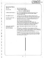
· ·operationarN·otes
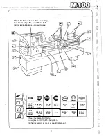
CHUCKS
FACEPLATES
COARSE FEED RANGES -
MICROMETER DIALS
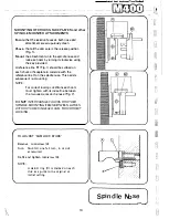
TAILSTOCK SET-OVER
ADJUSTMENT
CARRIAGE TRAVERSE
HANDWHEEL (25)
FEED TRJP DEVICE
- ' .
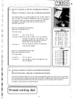
use only high speed tyl
. .
I
NOTE
MAXIMUM
SPEEDS
800 r.p.m. for 380rhm (15in) dia.
& . 400 r.p.m. for 580tm (23in) dia.
(i.e. when changewheels are.inverted as in set up
'G'
or
'H')
SHOULD NOT BE USED ON THE HIGH SPEED RANGE,
i.e. ABOVE 500 R_.P.M.
1
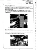
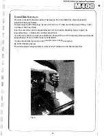
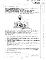
are direct reading (for w/ork piece diameter reduction on the
cross slide) and are of t�e friction-grip type for easy index settings
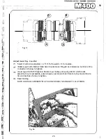
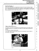
is provided in the form
df
socket screws (28) mounted
one
each
side of the tailstock bod� - a similar but 'location-screw' is
provided in the rear face of the body.
Set-over adjustment is Jchieved as follows:
Unclamp tailstock-lever;(20) and bolt {22). Slacken rear
'location-screw' (say on� half turn) then simultaneously slacken
one 'set-over screw' anc:11 tighten the other until the required
setting is obtained. Retighten the rear 'location-screw'.
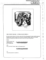
may be disengaged by dulling it outwards from the carriage
fac�.
d
· · ·
I
d · h
·
h' h
ff
d
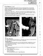
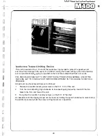
a tnp ev1ce 1s incorporate in t e carnage w 1c a or s
protection against acci�ental overload and also permits feeding up
to fixed stops with autbmatic dis-engagement; the trip load setting
is by means of the knu�led dial (27) on the apron.
It is recommended thaJ the dial setting be selected to suit th�
particular cutting load Jondition and not permanently adjusted to
its maximum load settif g otherwise premature wear to the feed
dr_ive components will rsue,
·
-.
-I-
15
Summary of Contents for M400
Page 1: ...420mm 16 1 2 heavy duty centre lathe Operations Manual info harrisonlathe com 800 575 2843 ...
Page 6: ... t _ ___ 1n_s_t_a_lla_ t_io_n___ J 3 ...
Page 14: ... 2 I _ N I r 1 __ lilt n I I 1 II CJ t k J 29 1 Jit S fi IZ n I 28 i i i Ii ...
Page 19: ...I i f n u 17 Thread cutting ...
Page 25: ...i _1 L l fi l l b f_ _ _1 1 J 0 U C l 23 ____J Maintenance i I i ...
Page 33: ...n td j t L f _J r i J Llf J I 7 r l LJ __ P_a_rt_s_ _s_e_c_ti_o_n __J ...
Page 36: ... _ d i I O i I L l LJ 400 4 79 t M8x30 FV D001H2093 D272H1002 M16x75 FH r l M16 FN 35 V 401 1 ...
Page 46: ...t 1 l 4 79 403 050 403 051 A03 058 SP 996 M12 1 L D4o t 45 SP996M12 j 03 053 403 3 ...
Page 52: ...M8 Fl 1ETRIC J0 4 111 7 16 50 813 30 4 160 304 162 404 5 ...
Page 66: ...M20 FH A 02O WN 411 028 1 411 025 4 11 026 411 14 64 J ...
Page 67: ...r 1 r J M16x60 FJJ 411 013 65 411 012 411 010 411 011 411 16 ...
Page 68: ...__ 411 052 66 411 050 41i Q53 411 31 i I J 1 t 1 I ...
Page 74: ...411 200 411 202 M10 Fll 411 205 0401H0001 72 411 204 M10x35 FY 3 411 67 ...
Page 83: ... LJ l J t f 1 I i 1 i J r s 0 i _____ _II j 1 J J 9 8 9 0 5 i 1 1 l s s I r i ...

