MIXBUS VBM
2 December 2021
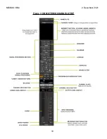
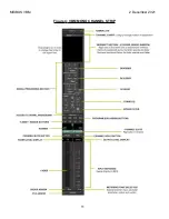
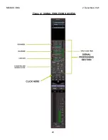
shows details of the channel strip signal processing section. Features of the
processing section are as follows.
Input gain trim: the slider on the right sets the input gain to the processing section, it has
a range of –20 to +30 dB of gain. This control should be the first step in balancing a mix
since it will facilitate managing mix minus and program levels. Beside the gain trim
control is a meter indicating signal presence and level, it measures at the channel strip
input before the fader or any plugins. Only one meter bar is displayed, on a stereo input
strip it will indicate the level of the sum of the 2 input signals.
De-noiser: The denoiser removes unwanted broadband noise and is tailored for use on
dialogue. The knobs adjust the depth of the denoising in the high and low frequency
bands, with a range of 2dB to 18 dB. The "Noise" button turns the processing on and
off. The slider on the left adjusts the overall degree of the de-noising from 0dB to –40
dB. The meter bar indicates the instantaneous amount of the de-noising.
De-esser: The de-esser has a range of 2dB to 18 dB attenuation adjusted by the
"Depth" knob. The Frequency knob adjusts the de-essing corner frequency from 500 to
4 KHz. The "Ess" button turns the processing on and off. The slider at the left adjusts
the de-essing threshold. The meter bar indicates the instantaneous amount of the de-
essing.
Leveler: The Leveler is a compressor with a low fixed ratio and release time. It is
designed to gently smooth out the peaks in a wide range of signals. The slider on the
left adjusts the limiting threshold from 0 dB to -40 dB. The Attack knob sets the attack
time over a range of 4ms to 100 ms. The Gain knob provides makeup gain over a range
0dB to 20 dB. The "Lvl" button turns the processing on and off. The meter bar indicates
the instantaneous amount of gain reduction.
Equalizer: The 3 band semi-parametric equalizer operates over the following ranges:
o
LOW: +/-15 dB boost/cut over range 40 Hz to 400 Hz, bell response
o
MID: +/-15 dB boost/cut over range 200 Hz to 4 kHz, bell response
o
HI: +/-15 dB boost/cut over range 800 Hz to 15 kHz, bell response
High Pass Filter: 12 dB/octave filter adjustable from 200 Hz to 1 KHz
21
Summary of Contents for Mixbus VBM
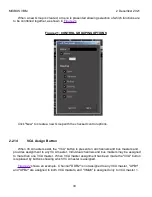
Page 1: ...MANUAL VERSION 1 5 DATE 2 December 2021 NOTES For VBM 1 2 release ...
Page 8: ...MIXBUS VBM 2 December 2021 Figure 2 VBM INPUT SECTION 8 ...
Page 10: ...MIXBUS VBM 2 December 2021 Figure 3 VBM STEREO CHANNEL STRIP 10 ...
Page 11: ...MIXBUS VBM 2 December 2021 Figure 4 VBM MONO CHANNEL STRIP 11 ...
Page 18: ...MIXBUS VBM 2 December 2021 Figure 11 CHANNEL EXTERNAL SEND 18 ...
Page 20: ...MIXBUS VBM 2 December 2021 Figure 12 SIGNAL PROCESSING ACCESS 20 ...
Page 23: ...MIXBUS VBM 2 December 2021 Figure 14 PROGRAM BUS ASSIGN BUTTONS 23 ...
Page 33: ...MIXBUS VBM 2 December 2021 Figure 24 VCA MASTER 33 ...
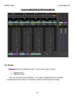
Page 36: ...MIXBUS VBM 2 December 2021 Figure 27 VBM BUS MASTERS 36 ...
Page 38: ...MIXBUS VBM 2 December 2021 Figure 28 PROGRAM BUS MASTER 38 ...
Page 42: ...MIXBUS VBM 2 December 2021 Figure 31 PROGRAM BUS MASTER SHOWING SENDS SECTION 42 ...
Page 47: ...MIXBUS VBM 2 December 2021 Figure 36 MIX MINUS BUS MASTER 47 ...
Page 51: ...MIXBUS VBM 2 December 2021 Figure 38 VBM MONITOR STRIP 51 ...
Page 53: ...MIXBUS VBM 2 December 2021 Figure 39 MONITOR SELECTOR 53 ...
Page 54: ...MIXBUS VBM 2 December 2021 Figure 40 MONITOR STRIP IN SOLO 54 ...
Page 56: ...MIXBUS VBM 2 December 2021 Figure 42 ROUTING TOOL 56 ...
Page 57: ...MIXBUS VBM 2 December 2021 Figure 43 SHOWING A PROGRAM BUS TO PROGRAM BUS CONNECTION 57 ...
Page 58: ...MIXBUS VBM 2 December 2021 Figure 44 MONITOR STRIP CONNECTION TO EXTERNAL INTERFACE 58 ...
Page 64: ...MIXBUS VBM 2 December 2021 Figure 48 ACE IFB SIDECHAIN INPUT CONNECTION 64 ...
Page 67: ...MIXBUS VBM 2 December 2021 Figure 50 ABOUT WINDOW END OF VBM USER MANUAL 67 ...

